Portal Help Center
Copyright ©
Triage
Happy Path - Order HQ on Citadel 1.1.2
Below are some tips and strategies for effectively using your Citadel powered locker. This will be updated as the product evolves.
General Tips
For the best experience, load one object at a time.
Do not load, remove, load items simultaneously. The system needs time to communicate state changes. Wait four to five seconds before reloading an item that was removed
Remove and clean the camera domes regularly.
Having a compartment blink may trigger unwanted presence detection in certain lighting conditions. It is recommended these settings are tested on location before live use.
Small or clear items will be difficult for the system to detect. Best practice is to use opaque and larger items that leave a significant footprint in the locker. The larger the footprint, the better detection will be.
When loading the locker, always aim for the center of the compartment. This improves detection.
Frictionless Tips
If a space is incorrectly detecting presence, place an item in the compartment, wait 5 seconds, remove it. It should revert to its ready state.
If a space will not detect presence, remove the item, wait 5 seconds and try again. This usually resets presence detection.
Shadows and unusual light conditions can sometimes trigger presence detection. If this is happening regularly, adjustments may be needed to the lighting, locker, and/or settings.
Clean and inspect the camera domes regularly. If they are scuffed, smudged, or scratched it will interfere with detection.
If the above steps have been completed and you continue to have issues with presence detection contact support.
Prescriptive Tips
The prescriptive load order can be customized upon request.
If a load skips an empty compartment, the system thinks that space is filled even though the lights might indicate the space is available.
Completing a prescriptive order without loading the compartment, or by using an item that does not meet the detection threshold will cause issues. While prescriptive does not use the camera detection for loading, it does when clearing a space. If an item is not removed from the compartment, or the camera dome is smudged or scratched, the space will not reset to “filled, closed, available”. To avoid this, do not load a prescriptive order without placing an item in the space, and do not use very small or translucent items.
Front Load Tips
Locate the kiosk in a convenient place where you can clearly see the contents of the locker.
You cannot load and pickup in a front load locker simultaneously. One single action must complete in its entirety before you start another.
Exterior Tips
Having both front and rear doors can cast shadows and affect presence detection. It is recommended that lighting conditions are tested and camera calibration and detection thresholds are set accordingly upon locker installation.
Device Configuration and Tools
Local Host - Tools and functions (located by typing “localhost:1880/ui” in the browser. If a tab exists and is not listed here it has no troubleshooting or monitoring function and should be ignored):
I&I - Illumination settings and testing tool
Cam Replacement - Review and configure camera IPs. Check real time images from camera’s of compartments.
TBL - Check and delete open schedules. Check and reset space statuses.
Cam Watcher - View presence percentages in compartments
Net Test - Test required network connectivity for deployments
Sam Tool (located here)
NUC - Used in End of Line. Do not use.
Config - Used to enable the troubleshooter. (legacy)
Citadel Troubleshooter - Used to see and delete schedules (legacy)
Cams - Used in End of Line. Do not use.
Locker Layout - Used in End of Line. Do not use.
Hlk Spaces - Used in End of Line. Do not use.
Spaces - Used to reset spaces (legacy) and set load priority (current).
SAM - Used to set illumination (legacy), open doors (legacy), view cameras (legacy), and view and calibrate camera masks (current).
Load Screen Settings - Used for device configuration of the following settings:
Default flow enabled. This will lock the device into one specific flow.
Enable multiple flows (selection IF default flow is off)
Associate ID password used in front load kiosk.
Frictionless load timer
Prescriptive load timer
Frictionless load message
Prescriptive load message
Frictionless toggle (off is prescriptive, on is frictionless)
Smart door (pickup) toggle on or off
Smart retries (door) toggle how many retires
Settings - Settings (legacy)
LED Test - LED test (legacy)
Lens - Used to check the health of citadel components
Locker status screen - Used to see which orders are loaded in the locker, identify orders stuck in a bad state, open doors, and reclaim orders.
Teamviewer - Used to log into the NUC remotely.
Simultaneous Actions
Concurrent actions will occasionally result in an unhappy state. Multiple improvements have been made to mitigate this issue but it is still possible for errors to occur. It is best practice to wait for the current action to complete before beginning another. Examples of concurrent actions include:
Picking up and delivering an item at the exact same time
Removing (reclaiming) multiple items from multiple orders at the same time
Removing and loading in quick succession
Multiple Compartment Orders
The maximum amount of compartments supported in one single order is 3. Any more may result in an unhealthy state
Rebooting The Locker
Most bad states can be resolved by rebooting the locker but rebooting should be a last case scenario to fix any lingering issues.
For the best experience, clear out any non loaded items in locker compartments before reboot.
For the best experience do not place any items in the locker while it is rebooting.
Do not rock the power switch on and off. Turn the switch to off, count ten seconds, switch back on.
Use the primary power switch to reboot the locker. This should turn off and on any satellite lockers. If a locker does not power down, or power up, check the power cables and switches.
The locker has an average boot time of ~4 - 5 minutes.
Known Issues and Likely Causes
This is a collection of known and reported issues and their likely causes. The likely causes are ordered from most likely to least likely and should be investigated in that order. This page will be updated regularly as the product evolves.
Lights will not come on
Locker does not have power
A critical Citadel pod has not initialized
Hardware issues with the camera or illumination board
Lights will not change color
The space is in an unhealthy state
Order(s) tied to that space in an unhealthy state
The camera puck has crashed
Scratched or dirty camera lens causing detection problems
Processing error on load / cannot create orders
False detection in unfilled spaces
Space(s) in unhealthy state
Order(s) tied to that space in an unhealthy state
Simultaneous actions
Citadel pods have crashed
Processing error on pickup / cannot pickup orders
Order reclaimed due to bad detection
Order was not created properly (see Pickup Issues section)
Space(s) in an unhealthy state
Simultaneous actions
Citadel pods have crashed
Hardware issue (door not opening)
IEI Screen is blank
If the indicator is yellow, check the cat 5 and power connections
A critical Citadel pod has not initialized
Bad ATX switch
Defective IEI
Customer did not receive a notification
Twilio received and sent the message but the carrier did not accept
Twilio received message but did not send, or was delayed
Twilio did not receive notification from Order HQ
Troubleshooting
Use these steps and methods to resolve reported issues with the locker. It is important to get an accurate account of the situation before diagnosing any problems. Ask these three questions before you begin troubleshooting:
Is the issue present in the locker’s current state?
Are you able to currently use the locker?
What was the state of the locker when you discovered the issue (Heavy use? On reboot? Found it this way?)
Here are some tips to keep in mind while troubleshooting:
Always make sure the locker is clear and not currently in use before altering orders in any way.
Recalibrating cameras with a loaded compartment will break the camera. Always check to make sure a compartment is clear before calibration.
Use the Camera Replacement tool in localhost to check spaces in real time. Often you can diagnose issues just by viewing the space state (lens scratches/scuffing, debris in locker, incorrect lights, open doors, etc)
Use the locker status screen to see what the locker thinks is loaded. You can compare this to observations in the Camera Replacement tool to confirm discrepancies and begin diagnosing the issue.
Grayed out orders in the Locker Status screen indicate an order is stuck in a bad state. Deleting that specific order and resetting the space in the TBL tool will solve the issue.
If Teamviewer is not responding and you are unable to connect to the locker, the only two remedies are:
Reboot the locker and try again
Have someone on site connect directly to the NUC with peripherals
To check current system settings visit this URL
To check current illumination settings you can use the illumination tool in local host, or visit this URL
Light(s) are not on
If a customer is reporting that light(s) are not coming on in the locker, users can take the following steps to resolve the issue. These steps assume the customer is not actively using the locker, and have no active orders loaded. Start at step 1, and follow the subsequent steps until the issue is resolved or referred to Veritas Automata for further investigation.
Verify the locker and its satellites are receiving power. Verify all connections are solidly docked
Access the NUC, then use Lens to verify all pods are up and running
Make sure all spaces are free of items
Access the TBL tab in local host:
Check for open orders and spaces not “unfilled, closed, available”
IF THIS CUSTOMER IS NOT INTEGRATED delete any open schedules
If this customer is integrated contact Veritas Automata before deleting schedules
Reset all spaces to unfilled, closed, available”
If any non Puck pod is crashing reboot the locker
If the pod is still crashing after reboot contact Veritas Automata
If the Puck pod is crashing terminate it by removing it and allow it to reboot
If the Puck does not recover from its crash loop, check the following:
The Camera Mask - A blank or corrupt mask will cause the Puck to continuously crash. You will need to verify the corrupted mask ( represented by the complete lack of a mask in the mask.png file) and then copy and paste another healthy mask. To replace the mask:
Use the command prompt to go to /var/lib/rancher/k3s/storage and locate the Puck with a healthy mask
Copy that mask file and replace the corrupted mask file using cp -f [original file] [new file]
Once the mask is replaced, restart the Puck
If it boots up, verify the mask with the SAM tool and recalibrate
Inaccurate Puck IP Address
Check the Puck stream URL by going into Lens & Deployments & and and edit the file
Scroll towards the bottom and look for the value RTSP_URL
The line below it will have a value of an IP address and it should read rtsp://192.168.100.1XX:554/stream1
Replace XX with the corresponding numbers associated with the position IP address. For example A1 (Puck 1) will be 192.168.100.131, A2 (Puck 2) will be 192.168.100.132, and so on
If the Puck does not recover after these steps, please contact Veritas Automata
If no pods are crashing and the light in the compartment is still off, use the I&I tool to manually force the compartment to change color.
If the lights still fail to turn on, it may be a hardware related issue.
Light(s) will not change color
If a customer is reporting that light(s) are not changing color, users can take the following steps to resolve the issue. These steps assume the customer is not actively using the locker, and has no active orders loaded. Start at step 1, and follow the subsequent steps until the issue is resolved or refer to Veritas Automata for further investigation.
Before we begin to troubleshoot, there are a couple of important things to understand regarding presence detection:
In frictionless, removing an item, waiting several seconds, then placing it back in the compartment often can reset detection.
Using small or translucent items to test the locker is not ideal. Oftentimes these items will be too small to trigger detection. You can test item detection by placing the item in question in a compartment and viewing the Cam Watcher tool in localhost to see what the system is detecting.
Make sure all items are removed from the locker, then reboot the locker
Once the locker is rebooted, make sure all the pods have booted correctly in Lens
Access the TBL tab in local host:
Check for open orders and spaces not “unfilled, closed, available”
IF THIS CUSTOMER IS NOT INTEGRATED delete any open schedules
If this customer is integrated contact Veritas Automata before deleting schedules.
Reset all spaces to unfilled, closed, available”
Go to the Sam tab located in the Sam tool and verify the camera mask has sufficient coverage
If unable to view the camera image or mask, verify the Puck is running in Lens. If the Puck is in a crash loop return to the puck pod solution procedures
If unable see the camera image but the Puck is running, proceed to step 7
If the Mask does not cover sufficient area, recalibrate the camera
Verify the new mask by refreshing the page and clicking the image button again
Access the Camera Replacement tool at http://localhost:1880/ui
Go to the Cam Replacement tab
Verify camera IPs. Camera IPs start at 192.168.100.131 and should continue to match the amount of compartments in the locker system.
For example, a V3 107 will have camera IPs of 192.168.100.131 through 192.168.100.137
Camera IPs should also correspond to their respective spaces in a linear fashion
For example, 192.168.100.131 should always be assigned to A1, 192.168.100.132 should always be A2, and so on
If there are duplicate IPs, IPs missing, or cameras missing, users will need to reset camera IPs to their correct spaces. Users can reset the camera IPs by doing the following:
Reset camera IPs by assigning them the correct space. There are several ways this can be done but the most important thing to know is what space (A1, A2, A3, etc) users are looking at through the camera
The surest way, starting with the top left (from the consumer perspective), is to place a sheet of paper with the number 1 clearly readable from the camera tool. The space A1 should be 1, A2 should be 2 and so on. Use these pieces of paper as a guide to reset the camera IPs to their correct space. A Camera showing a 1 will be space 1, a camera showing 2 will be space 2 and so on
Once completed, refresh the IPs. All correct non duplicated IPs should be displayed
Light(s) come on in the wrong compartment
If a customer is reporting that loading lights are coming on in the wrong compartment it is most likely either false presence detection on an unloaded compartment, or a schedule/space stuck in a bad state. If a customer reports this issue, users can resolve this by taking the following steps:
Access the TBL tab in local host:
Check for open orders and spaces not “unfilled, closed, available”
IF THIS CUSTOMER IS NOT INTEGRATED delete any open schedules
If this customer is integrated contact Veritas Automata before deleting schedules.
Reset all spaces to unfilled, closed, available”
Check the Cam watcher tool while the locker is empty to see baseline detection thresholds. If one or more compartments are above 5% detection while empty:
Clean/replace the camera domes
Review the mask and recalibrate
If the Cam watcher is still reporting presence in empty compartments Veritas Automata will need to adjust the detection threshold.
Terminate the Puck in Lens that is associated with the space showing false detection
Review the camera IP’s and make sure they are set properly. (See Light(s) will not change color, section 8)
Cameras and Presence Detection
Camera domes that are scratched, dirty or are in any condition other than clean, free, and clear of distortions can cause a wide range of camera issues. To ensure proper device operation, please make sure to keep the camera lens and domes clean and free of debris. Abnormal lighting conditions can cause false presence detection. If a customer is reporting a compartment is consistently showing presence detection while empty, take the following steps to resolve the issue:
Access the TBL tab in local host:
Check for open orders and spaces not “unfilled, closed, available”
IF THIS CUSTOMER IS NOT INTEGRATED delete any open schedules
If this customer is integrated contact Veritas Automata before deleting schedules
Reset all spaces to unfilled, closed, available”
Go to the SAM tab in the SAM tool and check presence and camera mask coverage
Sometimes the camera images can be cached. If this happens, please refresh the page for an updated image.
If the camera mask is distorted, recalibrate the mask
Use the Cam watcher tool to see presence detection while the locker is empty.
If, after cleaning the domes and recalibrating the mask spaces that are still reading above 5% filled, contact Veritas Automata to increase the detection threshold.
If the space continues to show false presence detection contact Veritas Automata.
Error Messages
Processing errors and other error messages are common when something is not working as intended. In most cases these errors are either caused by user error, or are a symptom of an unhealthy locker state (open orders and/or incorrect space states).
Transaction canceled, no spaces filled - Caused by false detection, items removed while loading, or spaces in bad states
No spaces available - Only achievable in prescriptive mode when the user attempts to load and all the spaces in the locker are filled
Order ID already in use. Try another - Duplicate order ID used
Please see attendant - The order is in lockdown
Invalid code - This error can only happen on the HMI. It means that the order ID entered is invalid (IE not attached to an open schedule). Likely causes of an invalid code error:
The order was reclaimed
The user entered an incorrect code, or tried to combine multiple pickup codes
The user got an incorrect code from a third party integrator
The order was locked down do to surpassing dwell time
The order is loaded in another locker system
Processing Error - General error displayed on the IEI
Text Messages
Customers using text notifications have a different set of challenges when utilizing the locker. There are many different ways to utilize text messaging both integrated and non integrated. You will need to know which process the customer is using before you can accurately troubleshoot. Text messaging customers run into two basic issues:
The customer did not receive a text message
The customer’s pick up code did not work
In both cases the first question to ask is do we send the text message or does the customer? If we send the message, verify the message in Twilio. If Twilio confirmed the message was sent, verify the pick up code was correct by referencing the order in the locker with the code sent. If the customer sends the text message, refer back to their integration and make sure it matches the order in the locker.
Front Load
Front load systems behave differently than flow through systems. There are several important things to keep in mind when training staff and troubleshooting issues with a front load system.
You cannot, under any circumstances, load and pick up an order at the same time. You must completely finish a load/pickup before beginning another load/pickup. This is due to both functions utilizing the front HMI. This should be taken into account when scoping the work flow and expected volume of the locker. In most cases, this will be the cause of the locker being put into a bad state.
The IEI kiosk placement is key to success. Putting the IEI kiosk in obstructed or inconvenient places will increase the likelihood of failure. The ideal placement for the IEI kiosk is in front or beside the locker with a clear visual path to the locker. If the attendant at the IEI kiosk does not have a visual of the front HMI there is an increased chance of error due to simultaneous load/pickup.
If an item gets stuck in the locker you can retrieve it by doing the following:
If the item is in a space that does not have a failed schedule tied to it (no grayed out order ID in the Associate UI reclaim tool) you can simply click on the compartment in the front load Associate UI reclaim tool to open the door and retrieve the item.
If the item is in a space that does have a bad schedule tied to it take the following steps:
Access the TBL tab in local host:
Check for open orders and spaces not “unfilled, closed, available”
IF THIS CUSTOMER IS NOT INTEGRATED delete any open schedules
If this customer is integrated contact Veritas Automata before deleting schedules
Reset all spaces to unfilled, closed, available”
Go to the reclaim screen in front load Associate UI and click on the space to open the door and remove the item
Reboot the puck associated with the bad space
If an item is loaded in a space that is not lit in the “loaded” color it is a clear indication that something is wrong. A great training tip is to instill this in the staff operating the locker. If the space is not lit in a “loading” color, do not load it. If the space is not lit in a “loaded” color, the customer will not be able to pick up the item and get an invalid code error when putting in the order ID. Users will need to retrieve the item using one of the steps outlined above.
Smaller items, poorly calibrated cameras, or dynamic lighting conditions can cause an item in a compartment to reclaim. If this happens, it will be represented as the space being reset to the “available” light with an item still in the compartment. The order will be reclaimed. Users will need to follow the steps above to retrieve the item from the locker.
If a user hits the complete order button while the door is open, the order will be loaded. This is not recommended.
If a user attempts a pickup while smart load is active (door is open, compartment is lit a “smart load” color) it will result in a failed load and pickup.
On boot, if a compartment is stuck yellow (loading color) with nothing inside, take the following steps to resolve:
Go to the reclaim screen on the IEI/Front Load Associate UI
Click on the compartment that is showing the false loading color (yellow)
Open the door
Place something inside for 5 seconds, then remove
Wait for the space to be reset to the proper color (available)
Close door
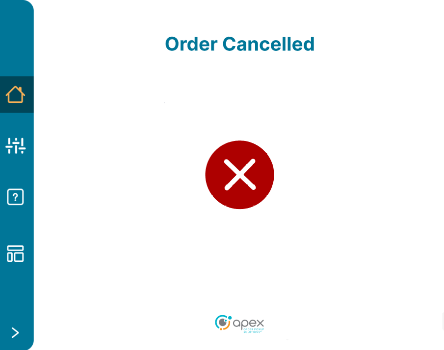
If a user accidentally hits “Add Compartment” instead of “Complete” after loading an item into a space, the proper course of action is to hit “Cancel”, which will cancel the order, and the user can start over again.
HMI / IEI
The HMI (customer facing pickup screen for V3) and IEI (employee facing loading screen, Kiosk, and both screens in EX) can encounter issues. Below are some known issues and ways to resolve them.
On boot, if the IEI screen is black and the indicator light is green, the IEI is in protected mode. The locker or the IEI (if accessible) will need to be rebooted.
The IEI has a zoom in/out feature. If you find the IEI is all white, or the interface is enlarged, simply use two fingers to zoom out similar to a tablet or touch screen phone
The IEI has been known to freeze completely when it is overheated. The locker or the IEI (if accessible) will need to be rebooted.
If the IEI has a yellow/orange indicator it is likely a hardware issue.
Lens and Pod Management
Important
Before accessing TeamViewer, please remember to log out of the TeamViewer session once work is completed! Staying logged in to a session may limit access to other users! This is critical to ensure that users have access to TeamViewer for Sev1 or Sev2 incidents that require immediate after hours access. There is a limit of 5 active sessions into a single or multiple NUCs. There is also a limit of 12 users that can be logged in simultaneously.
If the user cannot connect to a NUC via TeamViewer:
Insure the locker has power and is turned on through onsite communication
Insure the locker has an internet connection through onsite communication
If both of these are true, there are Two options
Have someone onsite connect to the NUC utilizing peripherals and restart TeamViewer
Reboot the locker until TeamViewer works
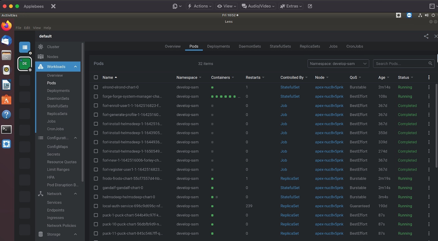
Launching Lens and Managing Pods
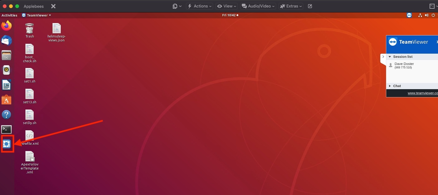
Login to TeamViewer
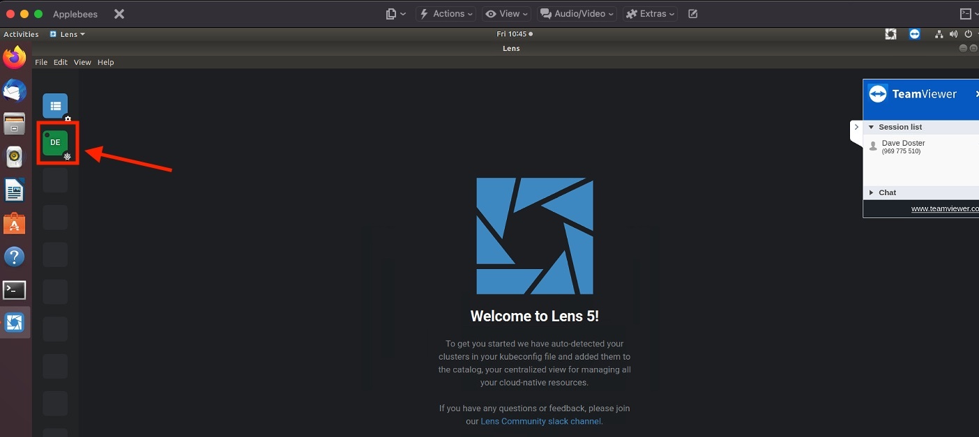
Click on the Lens Icon on the left side menu bar
Click the green DE button
Click on the Pods menu
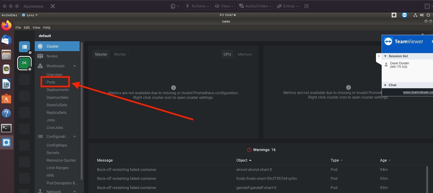
Users should see a list of Pods with their status and other critical information
Restarting a Pod
When a pod is not running, users can restart it. This is what a pod that is not running will look like:
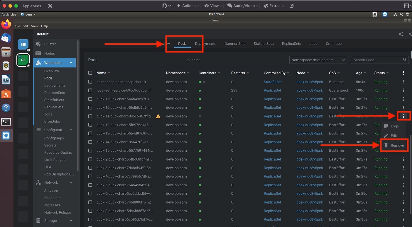
Make sure to be on the Pods tab. To restart a pod, remove the pod.
Other Tips, Tricks, and Information
Reset the cache on the IEI - this can clear multiple issues. To reset the cache on the IEI, turn it off and wait at least one minute before turning it back on.
While the locker can run offline with intermittent connectivity interruptions, it is not designed to run offline indefinitely. The machine will start to slow down after 50 orders, until an internet connection is reestablished.
The locker will not work without electricity
The locker cannot report data to the portal if it is offline
Short interruptions in electrical current to the locker will result in a bad state. It is best to reboot the locker entirely if interruptions in electrical current occur
Cleaning the locker regularly is required to maintain performance
Do not use the locker as a shelf to store items not related to an order
Device Operations
Latest Changes
Added NextUp Device Operations guide
Added Service Mode Application guide
Added Support Application Tool guide
Updated Support Application Tool guide content
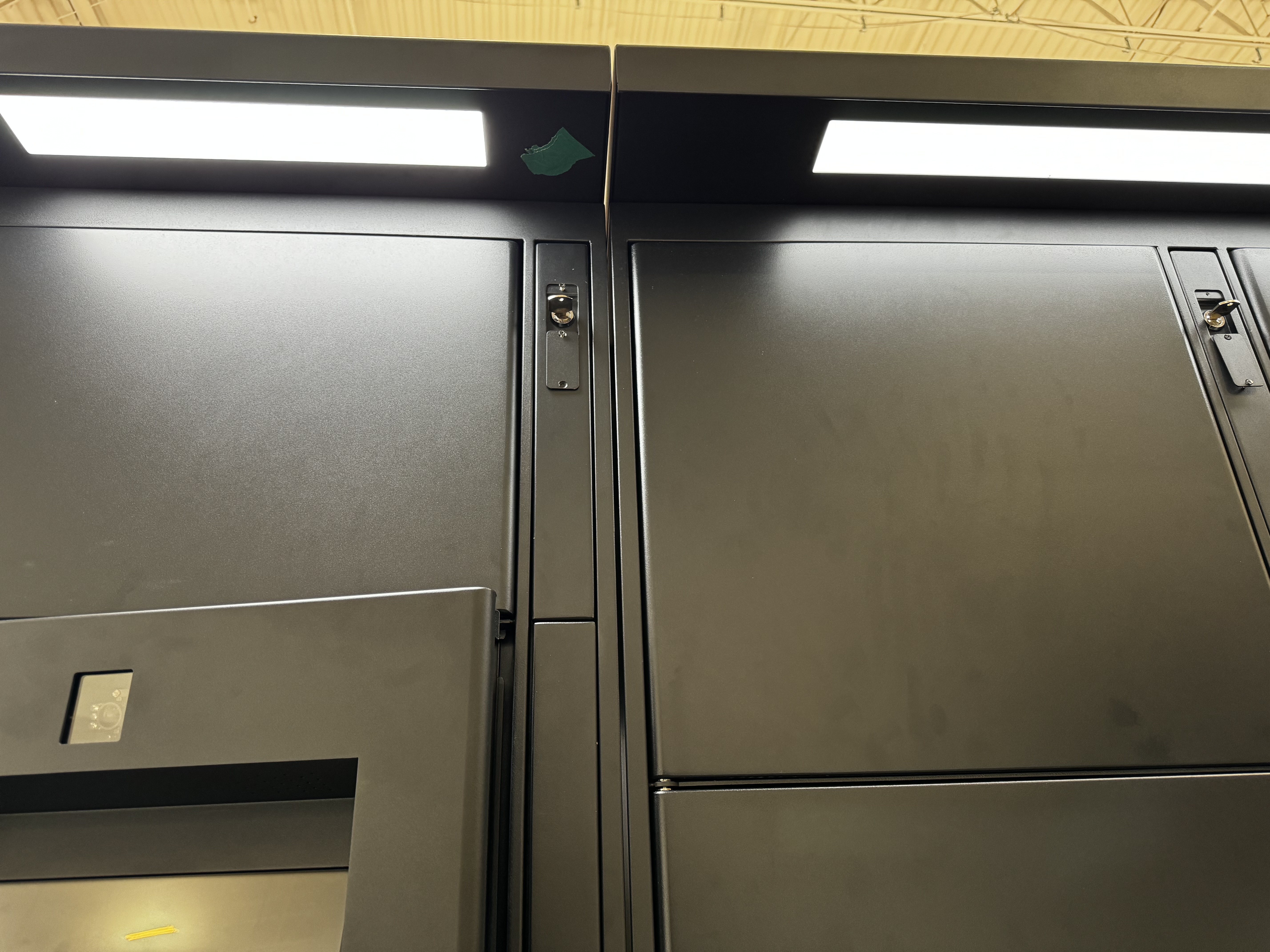
NextUp Devices
All NextUp devices are exclusively front load, operate only in prescriptive mode and use an IPC as the edge computing device.
Boot/Reboot
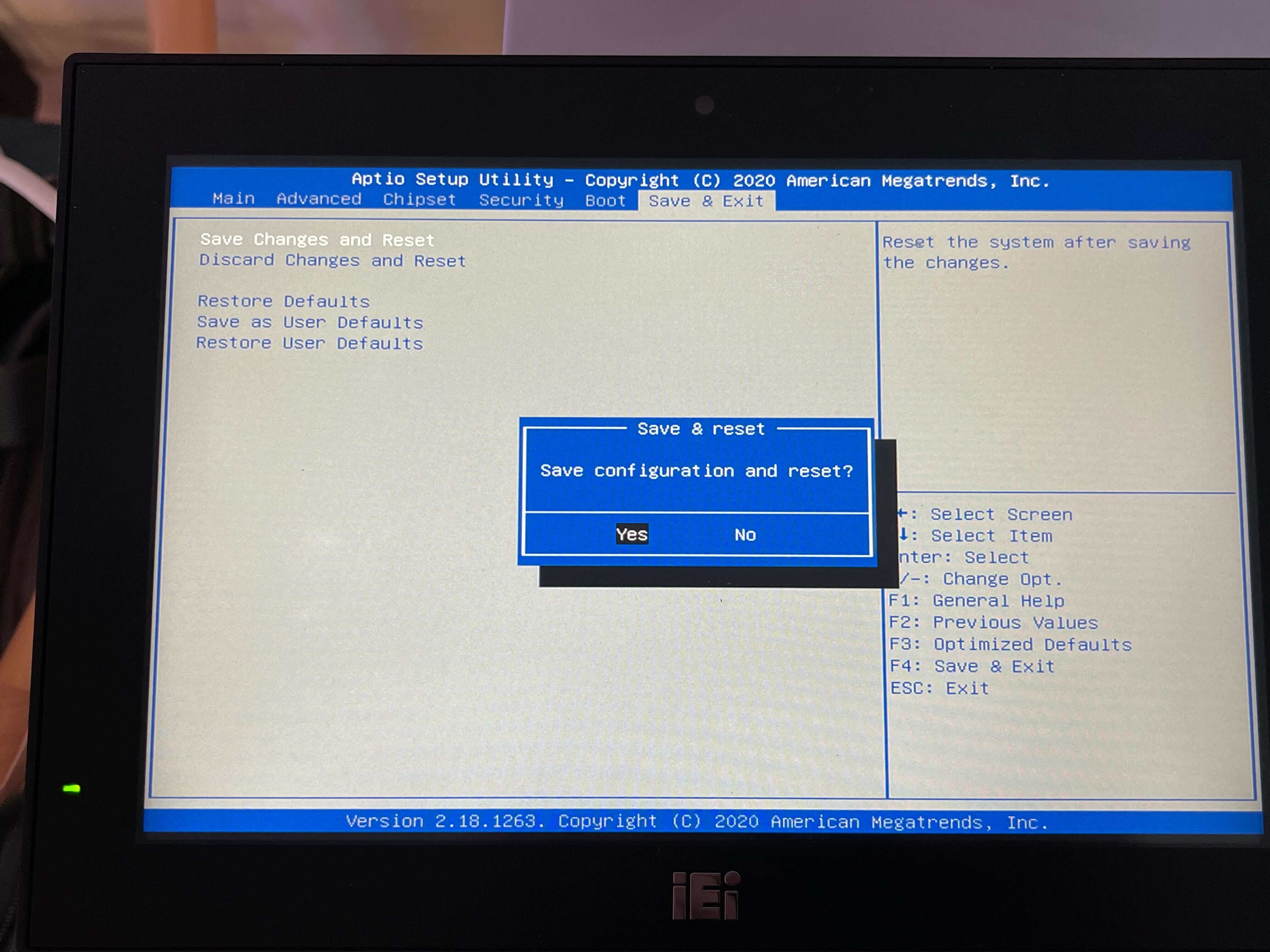
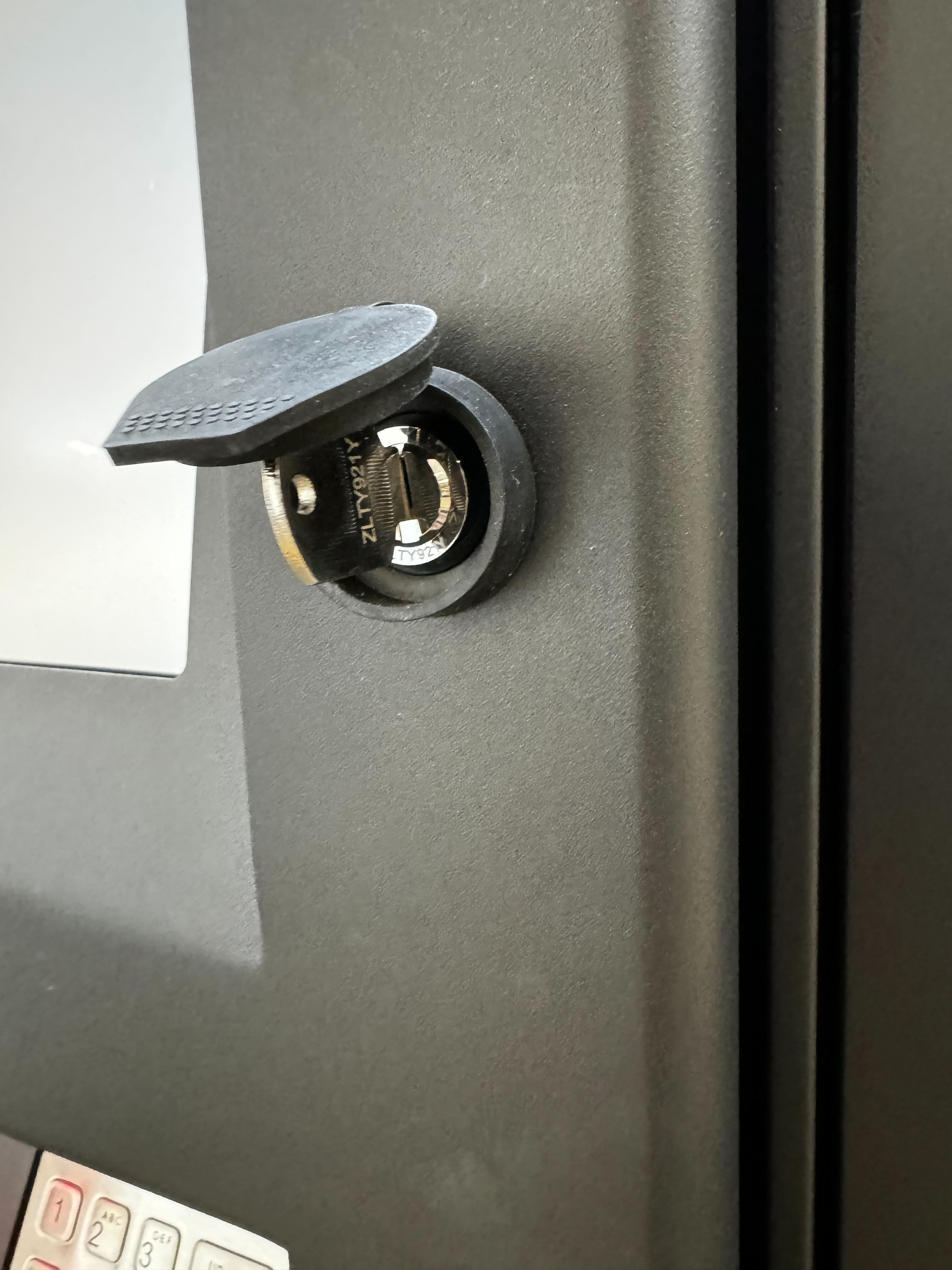
Unlock the main terminal compartment (the panel that the screen is attached to). Inside there will be a power strip. Flip the red power switch to the off position.
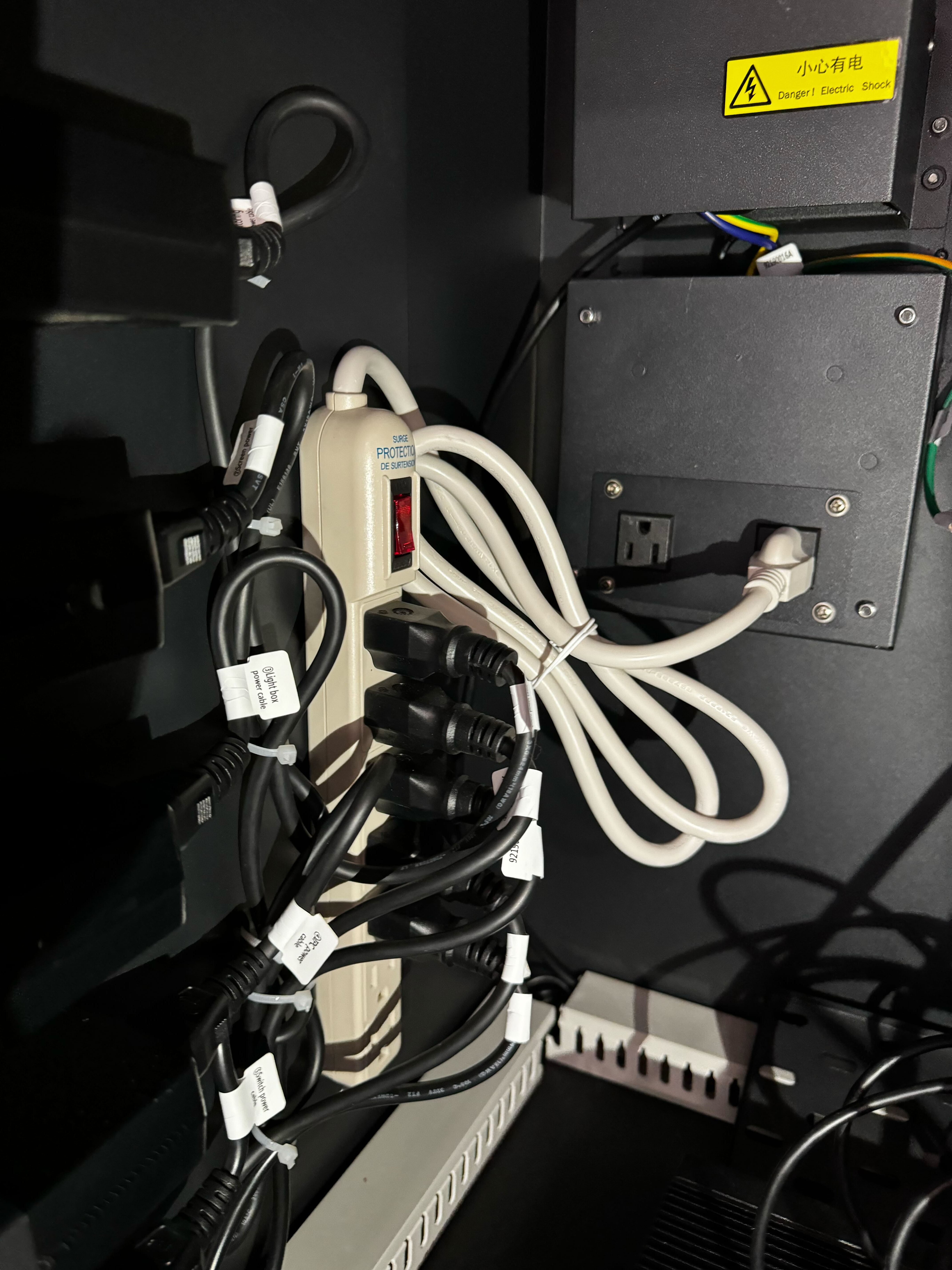
Wait at least 10 seconds. This will allow the capacitors to fully discharge and it ensures a complete shut down of all connected hardware.
Flip the red power switch to the on position. There will be an audible beep indicating that the boot sequence has initiated. The user will see the BIOS start screen. The overhead lighting will illuminate.
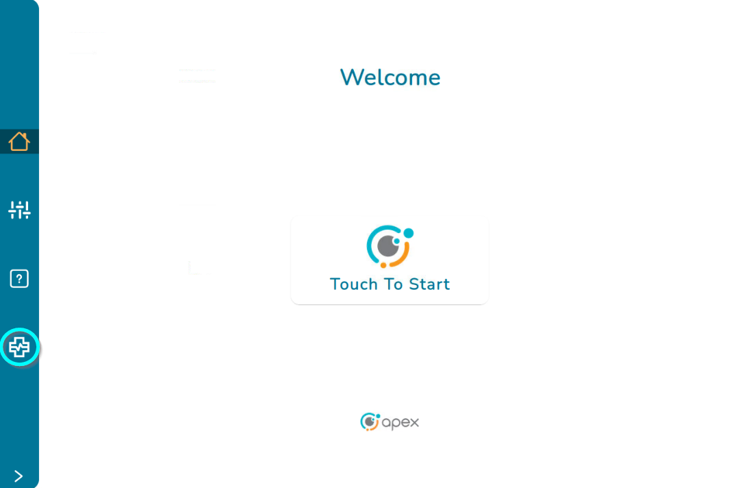
The user will see the splash screen followed by the touch to start screen. The total boot time is around 6-7 minutes (tested at 6 minutes 22 seconds).
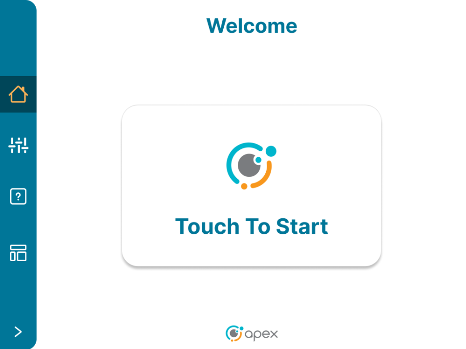
Loading
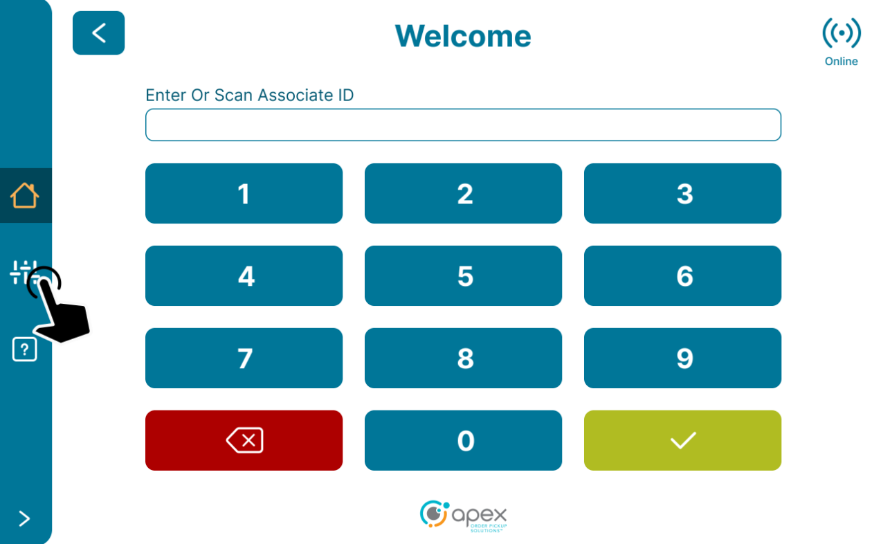
Users will start out on the Welcome screen. Follow the onscreen prompt for "Touch To Start".
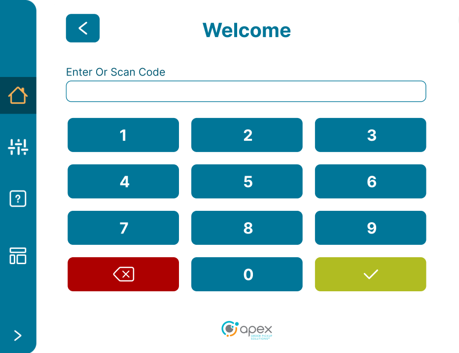
Users will be shown a keypad to enter or scan the load code.
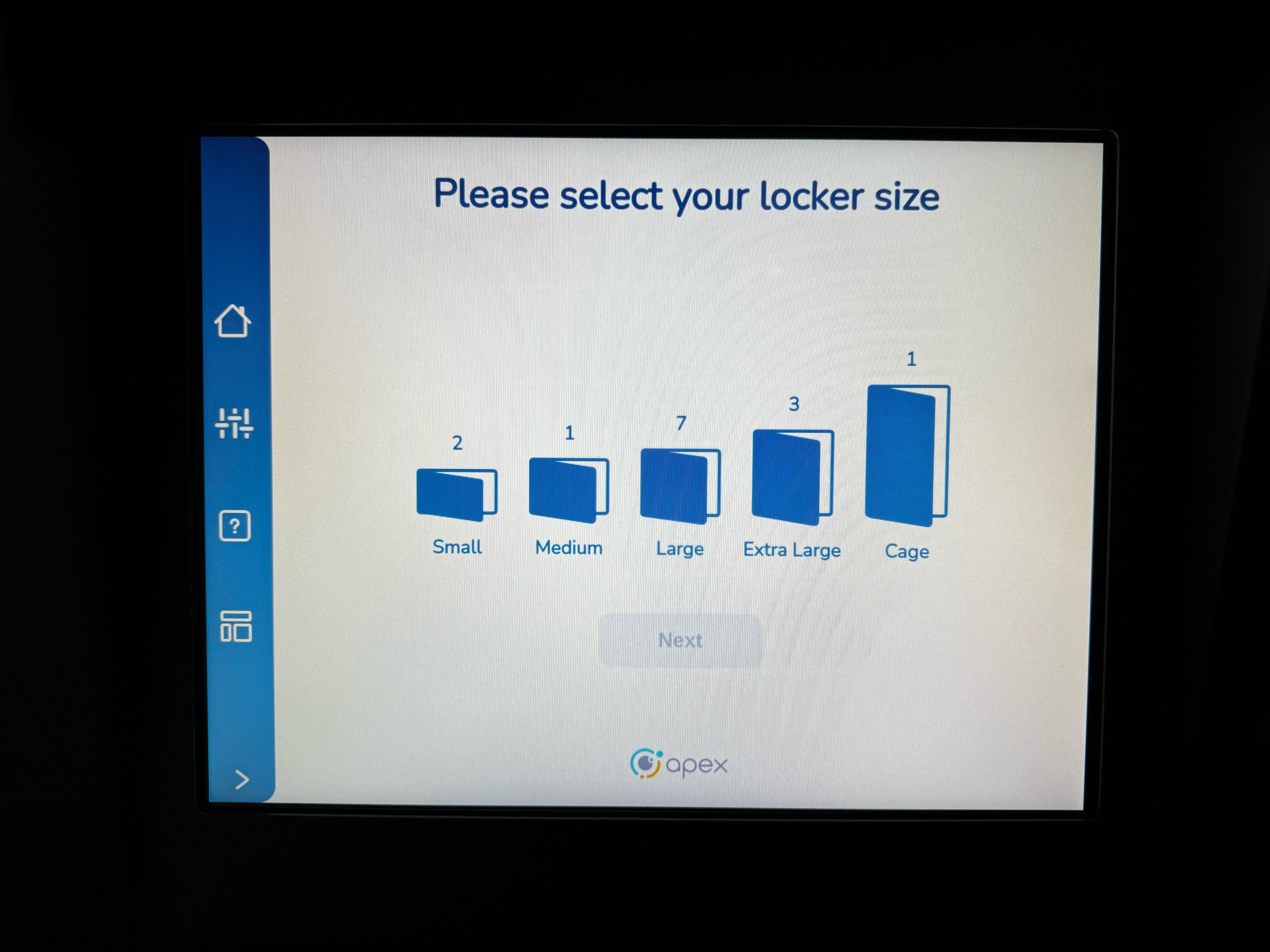
Select the desired locker size and press next.
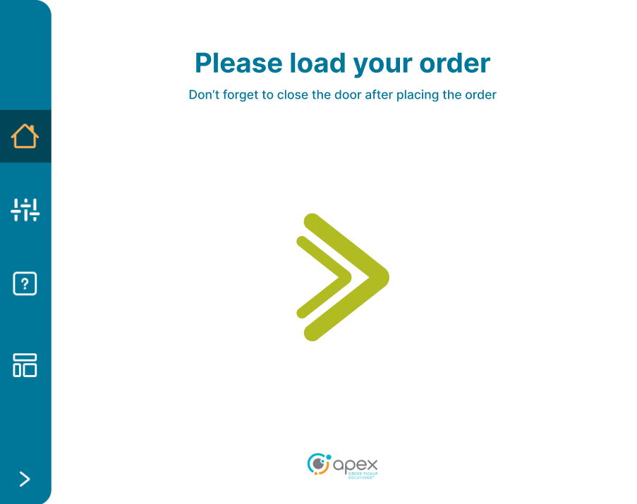
Follow the onscreen prompts to load the order item(s). The arrow will point to the direction of the position to be loaded into and that compartment will illuminate.
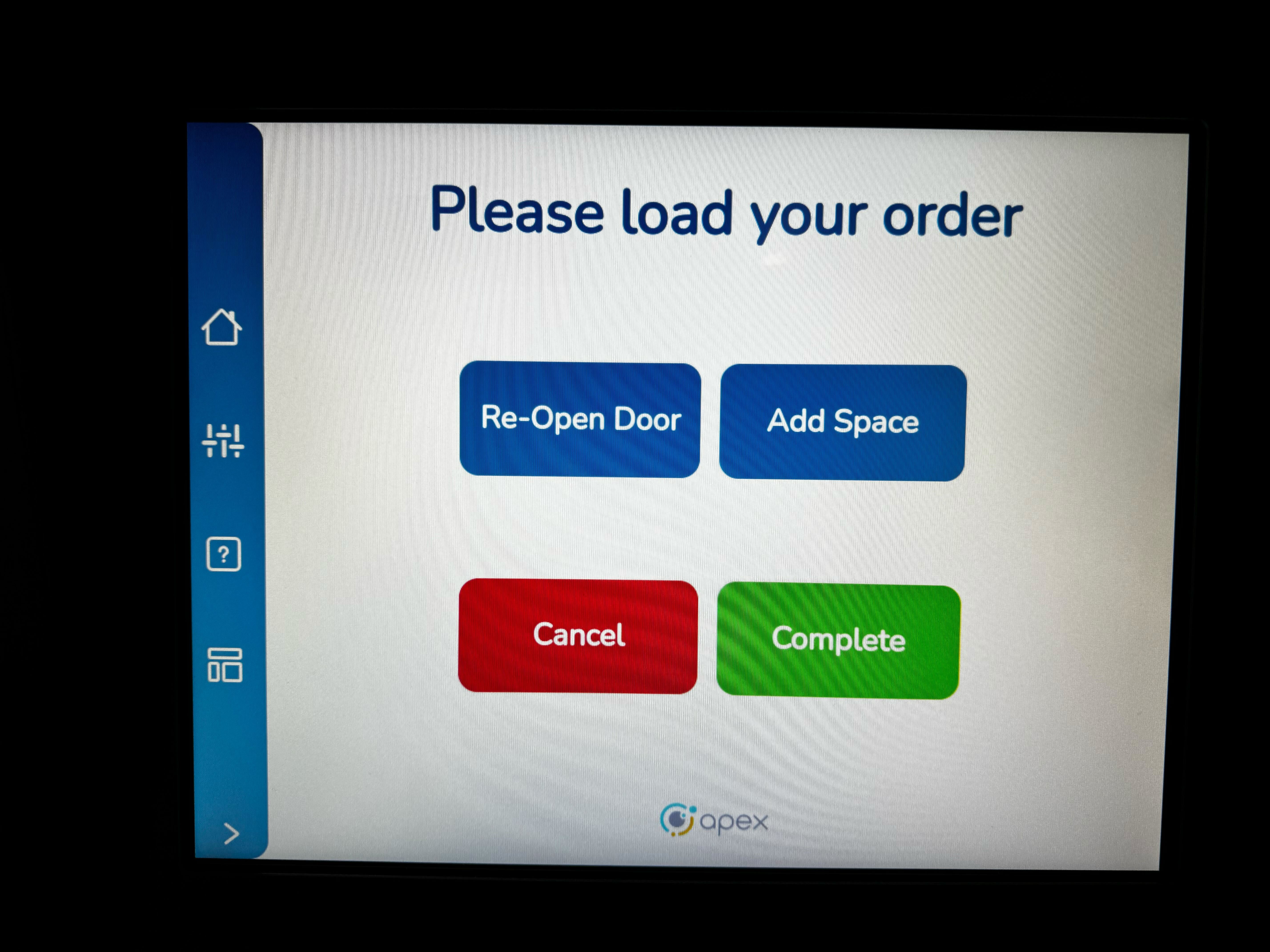
After the item is loaded, close the door. On the next screen, users can press the re-open door button to open the door, press the Add Space button for orders requiring more than one space, press the cancel button to cancel the load and return to the Welcome screen or press the complete button to complete the load process.
Pickup
Users will start out on the Welcome screen. Follow the onscreen prompt for "Touch To Start".
Scan or enter the pickup code to proceed. Depending on the device configuration, users will be shown a keypad or an alpha numeric keyboard.
Follow the onscreen prompts to pickup the order. The arrow will point to the direction of the compartment where the order will be picked up and that compartment will illuminate. If the order contains items in multiple compartments, the screen will show the number of doors left to pickup from.
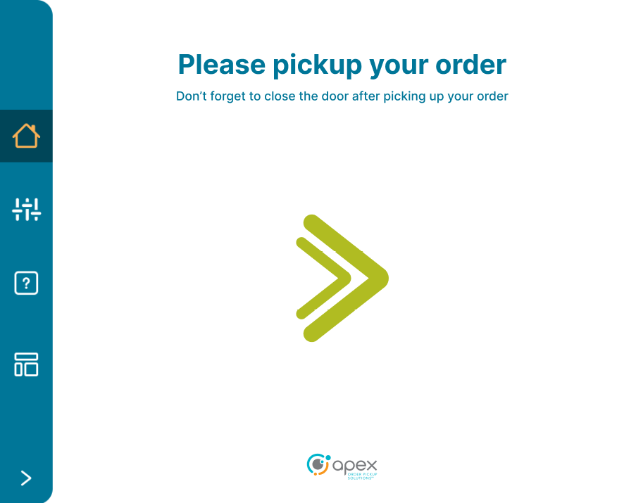
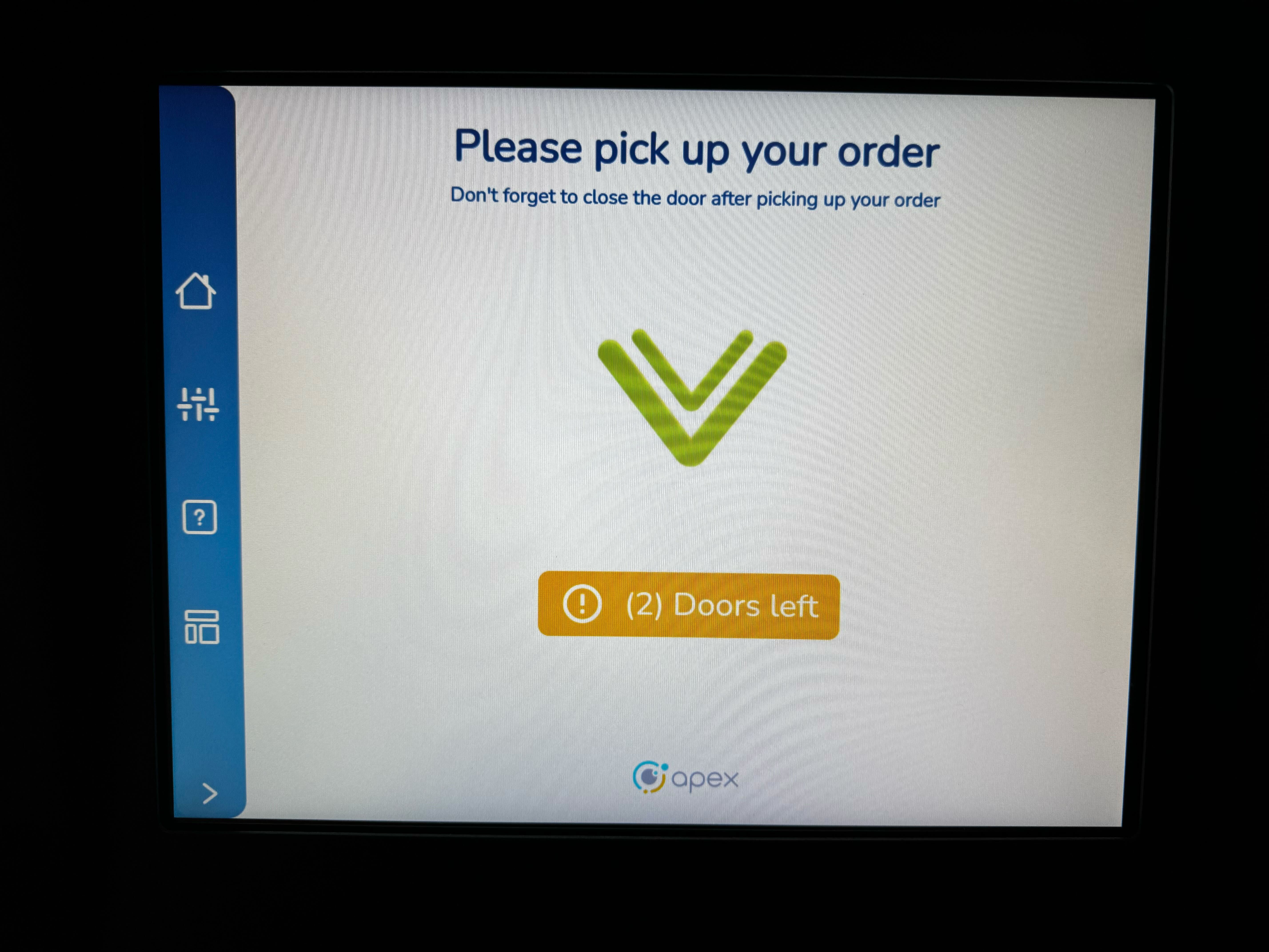
Close the compartment door(s) to complete the pickup process.
Reclaim and Reclaim All
Users will start out on the Welcome screen. Follow the onscreen prompt for "Touch To Start".
Scan or enter the pickup code to proceed. Depending on the device configuration, users will be shown a keypad or an alpha numeric keyboard.
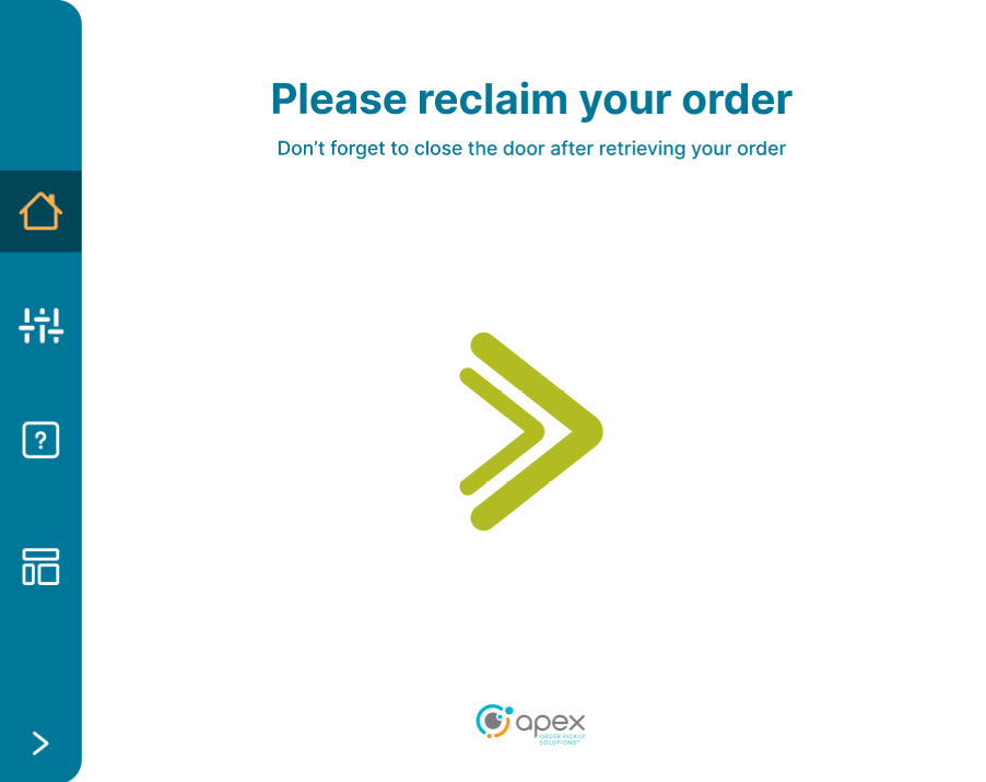
Follow the onscreen prompts to reclaim the order. The arrow will point to the direction of the compartment where the order will be reclaimed and that compartment will illuminate.
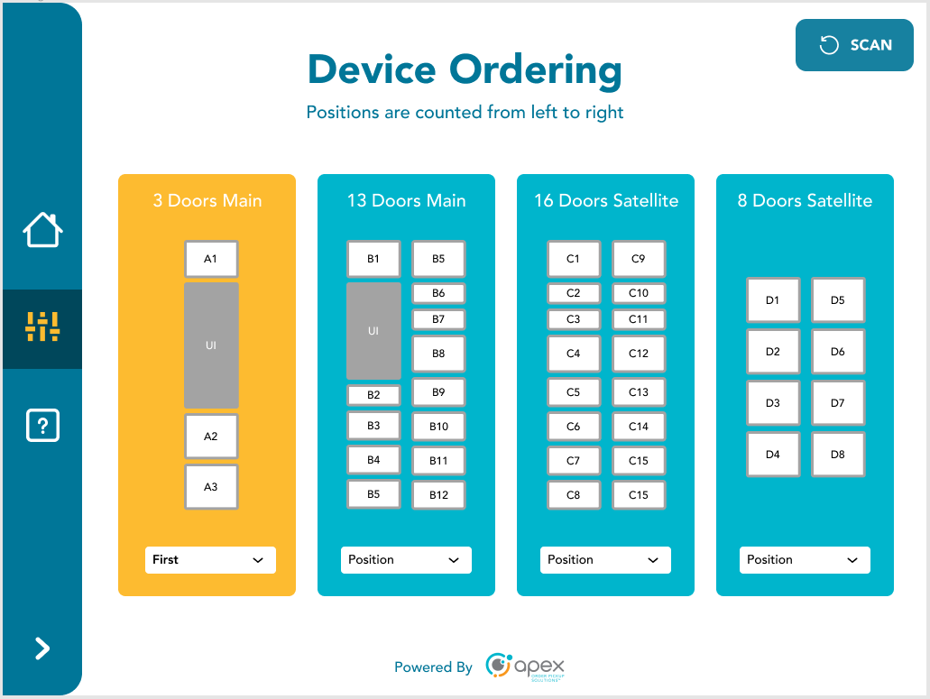
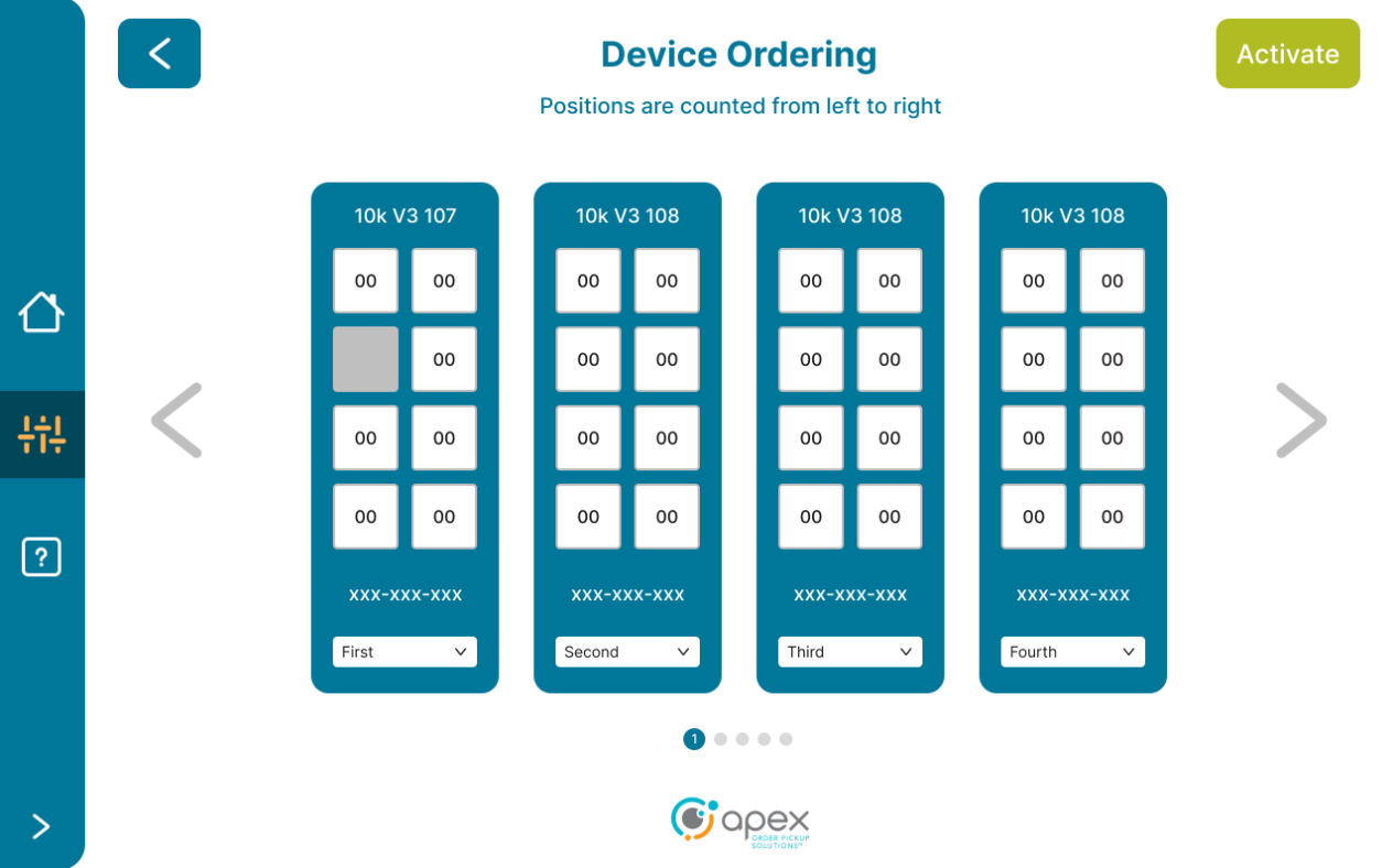
Device Ordering
Locker structures are determined by dial settings, which are physically set on the boards at the top of the lockers. The cage structure is set automatically and has no dial. If any of the information displayed on screen is incorrect, it is because the dial settings are incorrectly set. If device ordering appears to be incorrect, please contact an Apex Order Pickup Solutions specialist to remedy the situation.
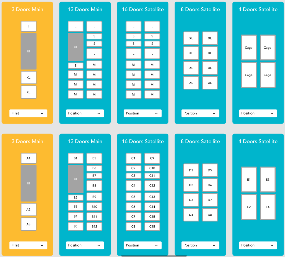
There are numerous device layouts available for site configurations. These device layouts include:
3 Doors Main - 1 large and 2 extra large compartments plus a user interface
13 Doors Main - 4 extra small, 7 small and 3 medium compartments including a user interface
16 Doors Satellite - 4 extra small, 8 small and 4 medium compartments
8 Doors Satellite - 8 large compartments
4 Doors Satellite - 4 extra large compartments
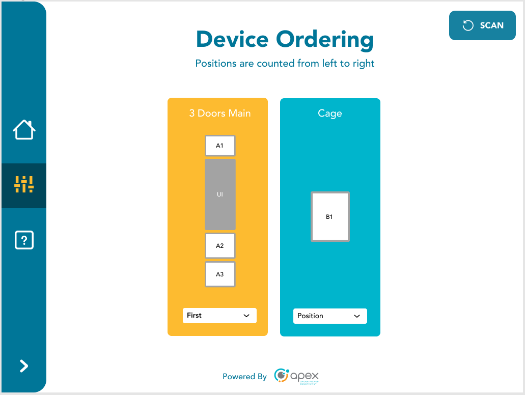
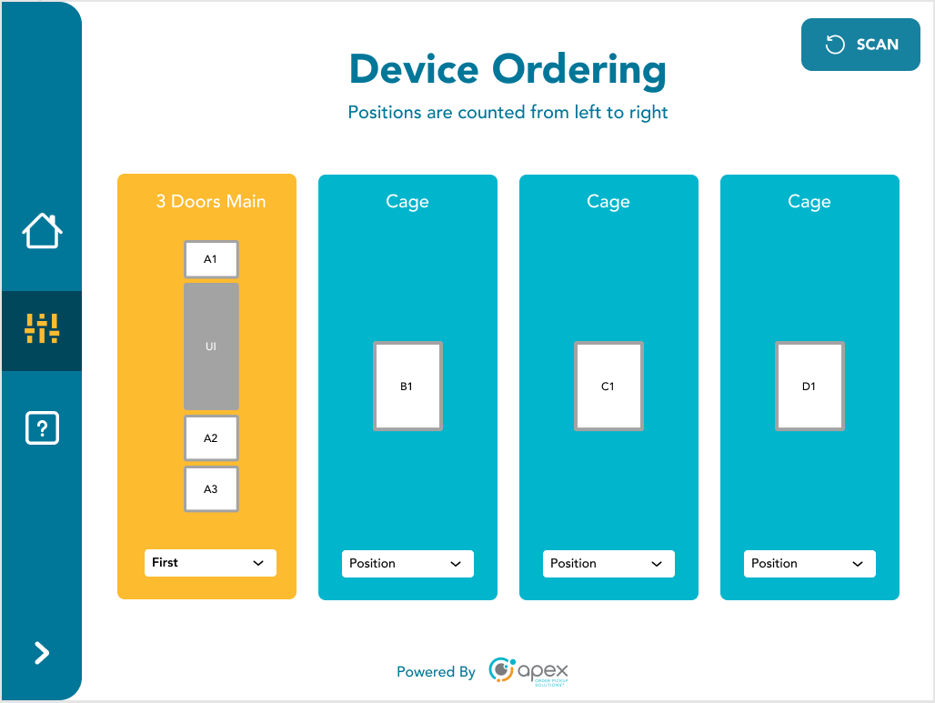
Cages have 1-8 various sized cages depending on configuration.
Here are some examples of site configurations that include multiple device configurations:
3 Doors Main + 13 Doors Main + 16 Doors Satellite + 8 Doors Satellite
3 Doors Main + Cage
3 Doors Main + 3 Cages
3 Doors Main + 13 Doors Main + 16 Doors Satellite + 8 Doors Satellite + 4 Doors Satellite + Cage
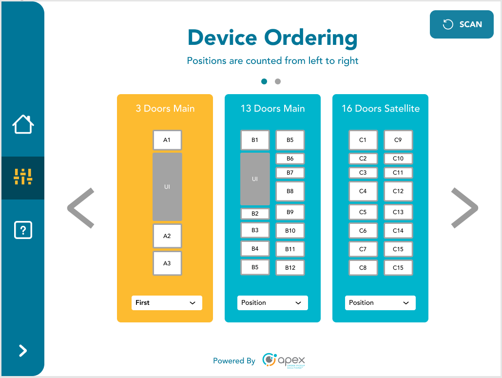
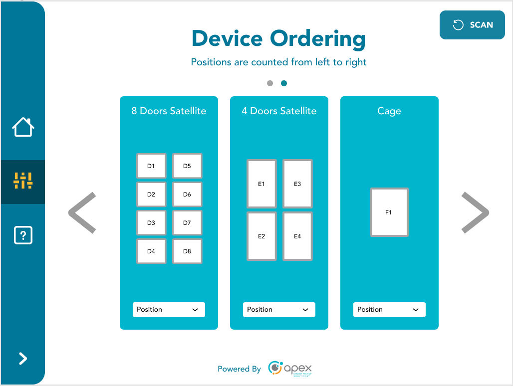
If there are too many devices to fit on a single screen, arrows to the left and right will appear allowing users to pan between each page. There will be dots above with a blue dot indicating the current page and a grey dot(s) indicating that there are other pages.
These configurations will be expanded upon as the product evolves and matures.
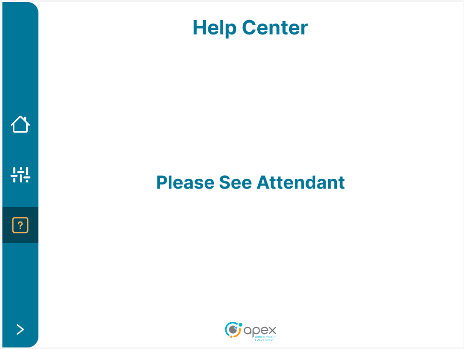
Help Center
At this time, the help icon will tell the user to "Please See Attendant". Future versions of the product will provide users with helpful information.
Service Mode Application
The purpose of the Service Mode Application is to verify that locker hardware is working as designed and to verify that any discovered problems are not hardware related. This application is not intended to be used for retrieving items out of a locker. The intended end user for this application is a technician, not a customer.
Touch the screen to start.
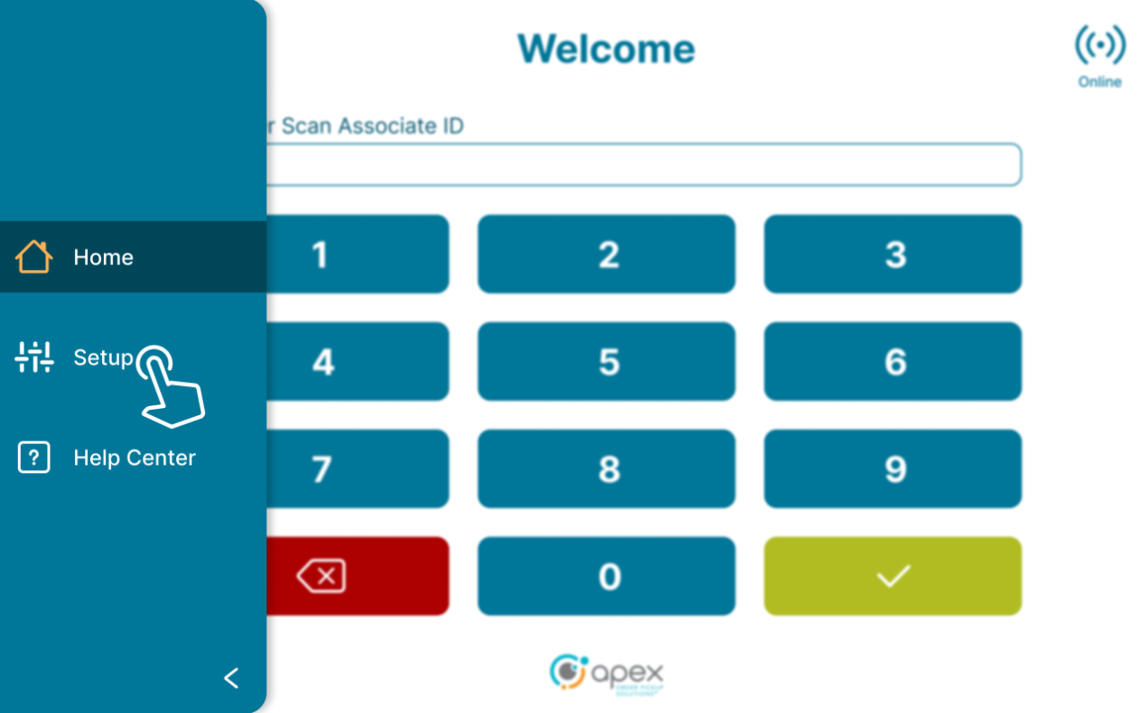
To access the service mode application, select the setup icon on the left side menu.
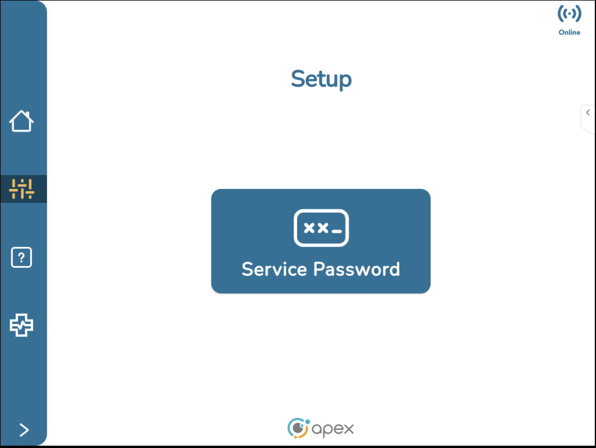
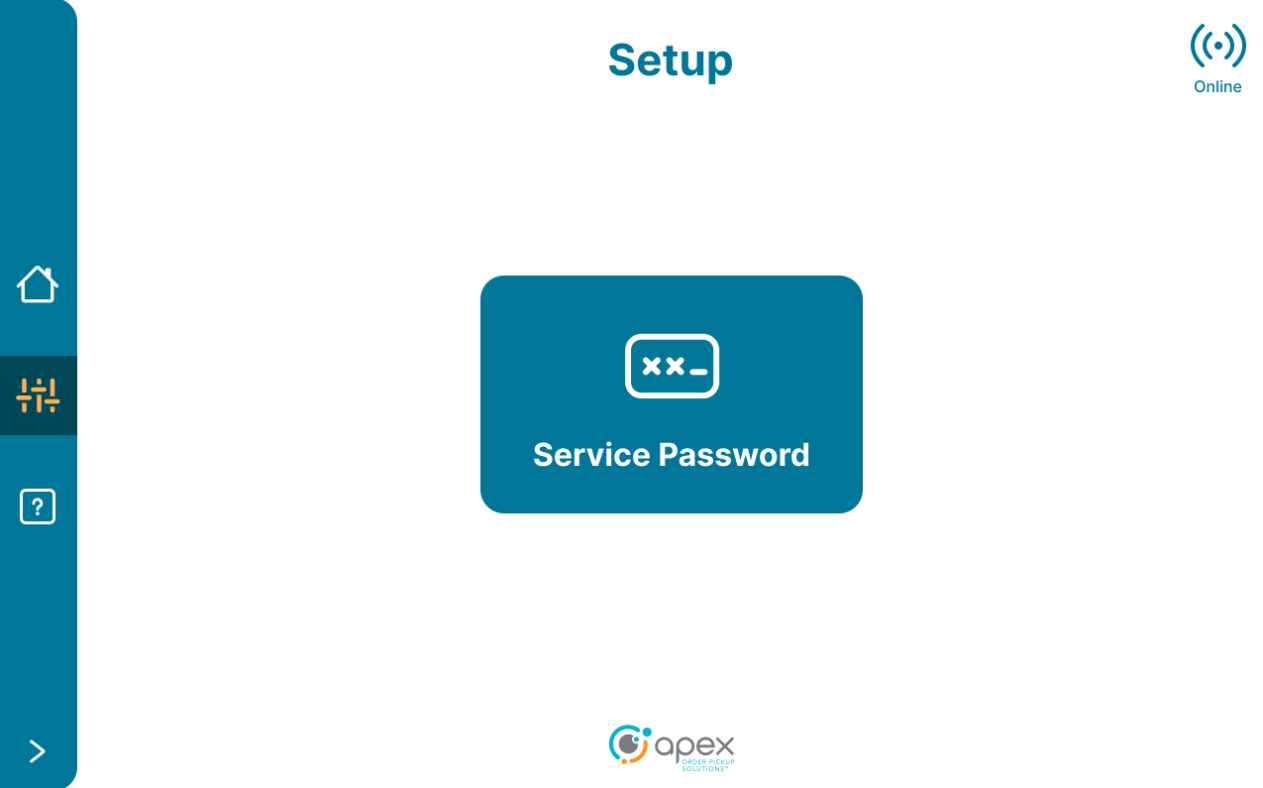
Enter the service mode password.
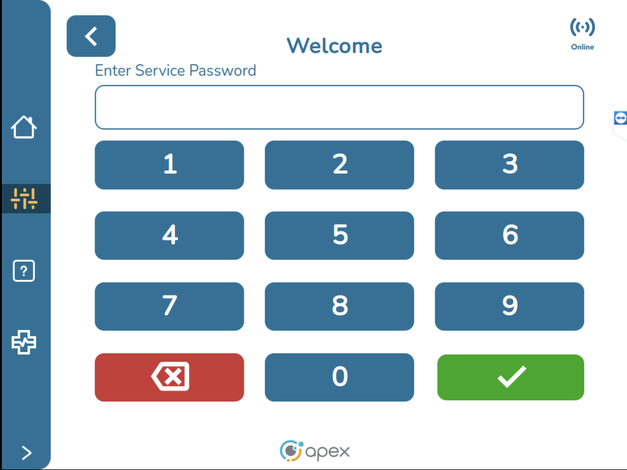
After entering the service password, the user is brought to the service mode application.
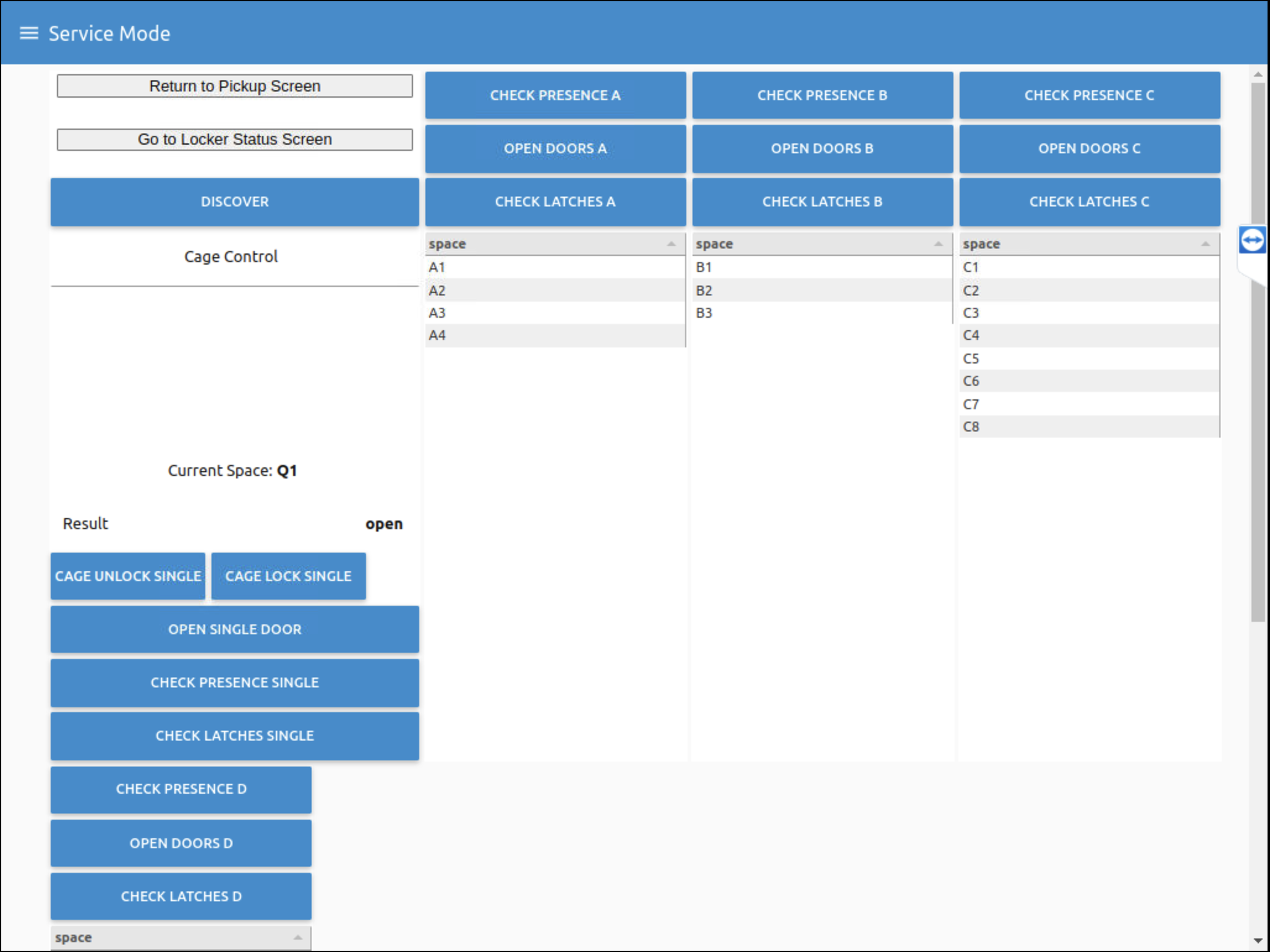
Application Functions
Once inside the Service Mode Application, users can take a specific action on a locker or a locker position to test.
Discover button - The application will discover in real time which locker devices are connected to it. In this example, the application will see locker structures A, B, C and Q (cage). These locker structures are determined by the dial settings which are physically set on the boards at the top of the lockers. The cage structure is set automatically and has no dial. If any of the information displayed on screen is incorrect, it is because the dial settings are incorrectly set.
Check Presence button - The application will check every space in a locker structure using the locker's sensors to show presence or absence for each position. To check presence on an individual position, tap the position to highlight it. Check that the current space displays the desired space, then tap the check presence single button.
Open Doors button - Each door in a structure will be opened. To open an individual door, tap the position to highlight it. Check that the current space displays the desired space, then tap open single door button.
Check Latches button - Each door latch status will be checked and their statuses will be displayed as open or closed. To check an individual latch, tap the position to highlight it. Check that the current space displays the desired space, then tap the check latches single button.
Note
A good way to test that the doors are operating correctly is to first press the check latches button with all doors closed. Each position should display a latch status of closed. Next, press the open doors button. Finally, press the check latches button again. Each position should now display a latch status of open.
There is a great deal of extra space in the Service Mode application UI. In this example there are 3 devices connected but the application is designed to support up to 6 connected devices. There is a right side scroll bar for when the number of connected devices exceeds what can fit on 1 screen.
Locker Status Screen
The Service Mode Application gives users access to the locker status screen. The LED circle at the right indicates green for success, red for failure and blue for neutral status when performing actions.
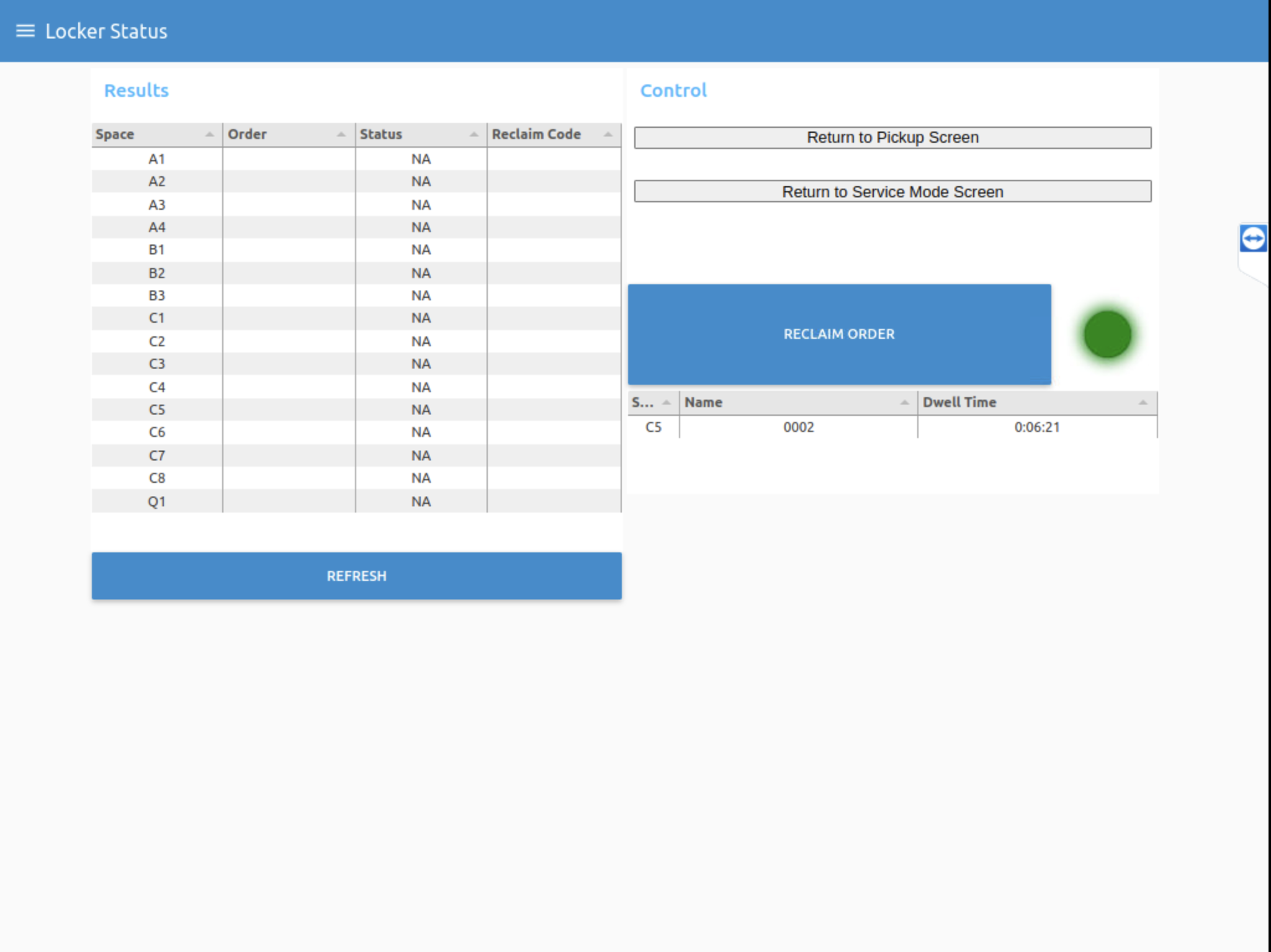
Users can tap the refresh button to show all the spaces in each locker and their current status.

In this example, position 5 on locker C is loaded. Users can tap on an individual space to get the order details for space name, reference ID attached to the order and dwell time. Users can reclaim an order from this screen. This is not a simple open door function, this action cleans out the order and puts it into a reclaim state.
The locker status screen is a quick way to not only see what is in a locker, but to also to remove orders in the event that a customer is unable to pickup an order for any reason (order locked down, no pickup message, never received message, etc.) an employee can access this screen within the Service Mode application and quickly resolve the issue.
Note
This is a temporary gap filling measure until this functionality is built in the Associate UI application.
Tapping return to pickup screen will exit the Service Mode application and return the user to the Associate UI Welcome screen.
Support Application Tool
The Support Application Tool is an application in the Associate UI and is accessible through the device's screen to Apex users. Currently it is only available for Order HQ devices, in the Associate UI context rear-loading and front-loading, but eventually will be available for NextUp devices. The primary purpose of this application is to provide background information for support users that helps them to understand the environment and any ongoing problems. It allows support users to clean up the system and provide solutions to prevent issues. This tool allows users to perform the following device actions:
Corroborate inconsistencies between orders and lockers
See the list of open orders
Delete open orders
Return a locker to its original status (unfilled, closed, available)
Update the threshold of a locker
Calibrate the mask of a locker
Confirm if a space is disabled or enabled
To access the Support Tool, login to the Associate UI and select the Support Tool icon on the left side menu.
The user will be brought to the Overview Screen.
Overview Screen
The overview screen is the landing page for the Support Tool.
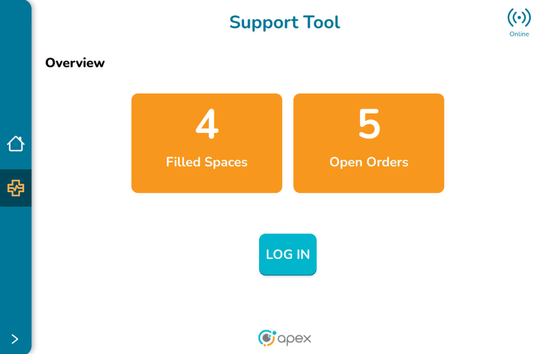
This screen provides a summary of the current state of the device:
Filled Spaces - This is the total number of spaces which are currently filled. This is given by the ratio between the Load Percentage and the Detection Threshold
Open Orders - This is the number of open schedules
Note
Filled spaces can be greater than, less than or equal to Open Orders. Usually the orders occupy just one space, so the Filled Spaces can be less than or equal to the Open Orders. When an order occupies more than 1 space, it could be that Filled Spaces are greater than the Open Orders.
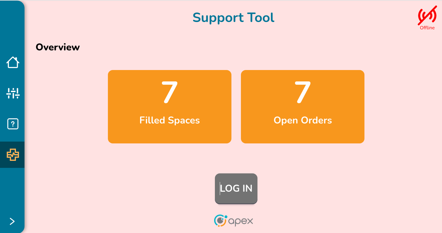
This screen does not provide enough information about possible issues or problems with the device and its orders. To get this information or fix a known issue, it is necessary to access the application. To continue using the application, the support user must be logged in. Click on the LOGIN button to continue to the Login Screen. If the device is offline, the Support Overview screen looks like the image below, indicating that there is a problem with the connection and the Application cannot be used. The LOGIN button is disabled.
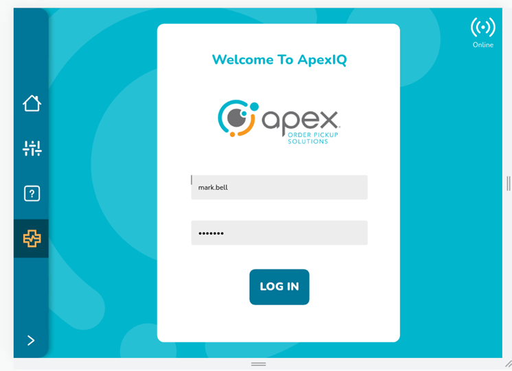
Logging in to the Support Tool Application
The user must have an account with access rights to access this application. Enter the user name and password. Then, click on LOG IN button to continue to the Support Tool Dashboard screen.
Note
Please create a Monday ticket to obtain credentials to access this application
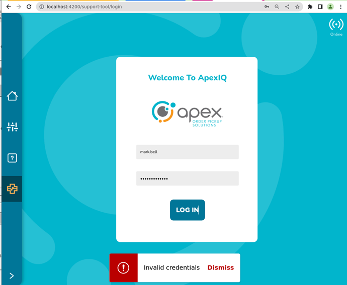
If the user provides the wrong username/password combination or invalid data, the error message "Invalid credentials" is displayed on the screen. Click on dismiss to close this message or wait a few seconds until it vanishes.
Once the user logs in, the session is active for 15 minutes. After this time, the message “Your season will expire soon, Do you want to extend your session?” is presented with the options to extend the session or not:
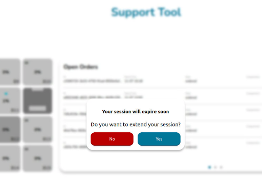
Yes - The message is hidden and the session is extended for another 15 minutes. At the end of the session the session expiration message pops up again.
No - The message is hidden and the session is extended for around another minute, so the user can continue interacting with the application. After that time the user is automatically logged out and redirected to the login page.
No Action Taken - The user is taken out of the application and redirected to the Login page.
Support Tool Dashboard Screen
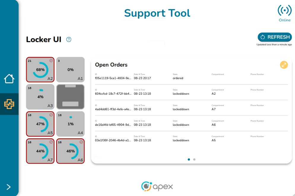
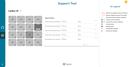
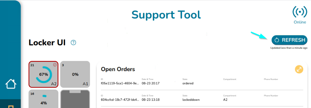
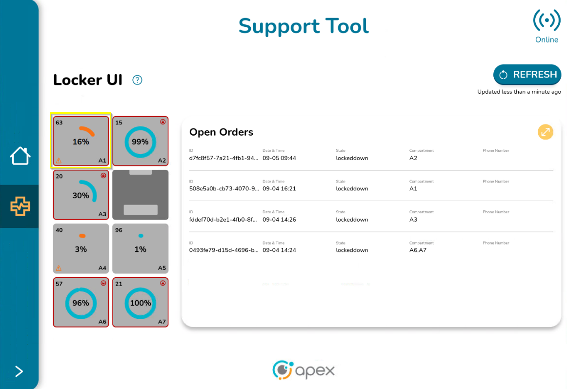
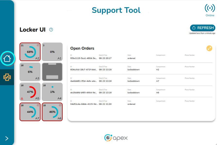
Once logged in, the main screen is displayed:
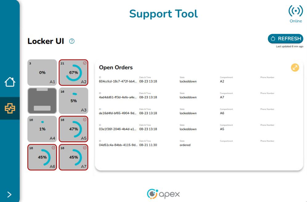
This screen is composed of 2 sections:
Locker UI - Displays the lockers of the device and gives users visibility to its current properties and status.
Open Orders - List of orders which are currently in an open status. An open order is an order for which its schedule is in Open status, that can or cannot be within a locker and is composed of dispenses (one in general). The most common statuses that identify an open order are: ready, ordered, loaded and lockeddown.
This screen also contains:
Available Help - Shows the symbols and images used to describe the status of a locker
Refresh Button - Updates the information on the screen
Online Icon - Indicates if the Support Tool is available
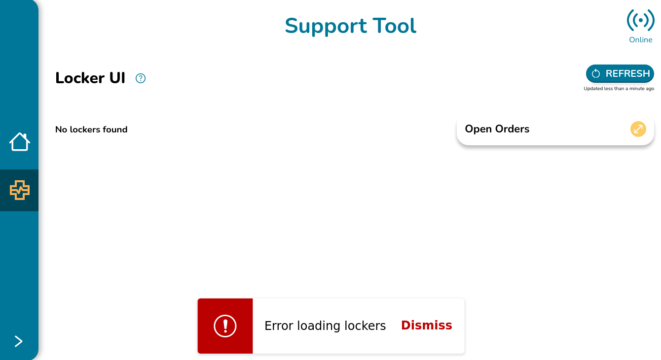
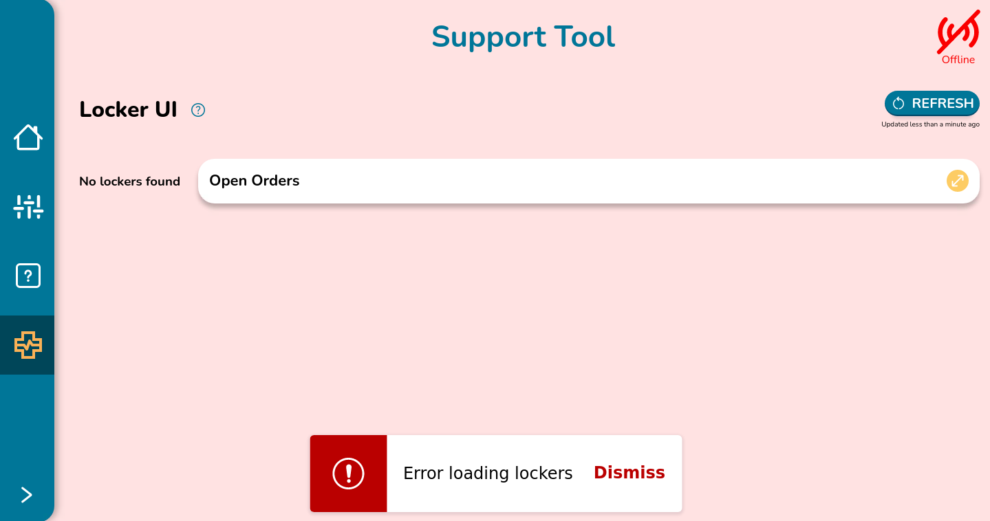
If there is a problem loading the lockers due to service not responding, the Support Tool Dashboard screen looks like the image below.
Locker UI Components
The Locker UI portion represents the device´s layout along with its lockers and the HMI. The locker layout changes depending on the particular Associate UI in use:
The locker layout on a Flow-Thru device displays the locker layout from the perspective of the rear side.
The locker layout on a Front Load device displays the locker layout from the perspective of the front side.
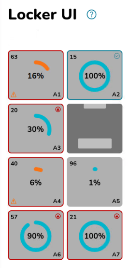
Below are examples of what the numbers and symbols represent:
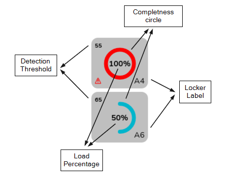
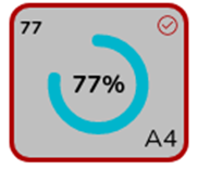
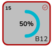
Locker Label - This is the label of the locker. The value in the bottom right is the locker label.
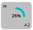
Detection Threshold - This determines the minimum amount of presence required for a position to be marked as filled. The number is represented by 2 digits. It comes from the backend and it is rounded to the nearest whole number. The detection threshold is set in the ApexIQ Camera Interface.
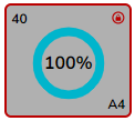
Load Percentage - This is the amount of filled compartment represented as a percentage. The number is represented by 2 digits. It comes from the backend and it is rounded to the nearest whole number.
Completeness of the Circle - Graphical representation of the load percentage.
Color of the Circle - Reveals the status of the space:
Blue - The space has everything in place, no issues present.
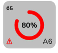
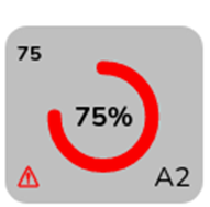
Red - Issues are present with an available space. Requires attention. The locker presents a warning icon.
Orange - Issues are present with an occupied space. Requires attention.
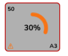
Example 1 - Given the locker A4 has a Load Percentage of 100%, the circle around it is complete. Since it is red, there is a problem to be resolved.
Example 2 - Given the locker A6 has a Load Percentage of 50%, only half of the circle is painted. Since it is blue, the space has no issues to be resolved.
Attention Sign - At the bottom left side of the space, some spaces can have an attention sign indicating that something is wrong with the space and action is required to resolve the situation.

Check Mark - At the upper right side of the space, a check mark may appear, signaling that the space is in good condition. It indicates that an order has been successfully loaded and no further action is needed to fix or adjust the space. The check mark confirms that the order is ready for pickup.

Lock Pad - At the upper right side of the space, a lock pad icon may appear, indicating that the space is in good condition and the order has expired, causing the state to be locked down. No further action is needed to fix the space. The lock pad icon signifies that the order is in optimal condition to be reclaimed.
Enabled Space - The spaces filled with a light gray color are the enabled spaces, meaning the spaces can be reserved or available and can have a schedule associated with them.
Disabled Space - The spaces filled with a dark gray color are the disabled spaces. These spaces do not have any order or schedule associated with them.
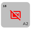
Broken Camera Image - A broken camera icon within any of the spaces happens when there is no information about the Load Percentage due to problems with the connection, the camera not working properly or a process is currently running so the service is not fully available.
HMI - Human Machine Interface (HMI) is a visual representation of the dashboard or screen used to control the device.

Below are examples of possible cases a user can find in the locker UI:
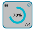
Spaces with Orders Associated
Spaces with a dispense in a LOADED state with "loadPercentage" greater than or equal to “detectionThreshold” (Filled space)
Locker representation:
Blue border
Check mark at the top right side
Detection threshold (upper left side)
Load percentage (centered)
Circle around the percentage is colored blue
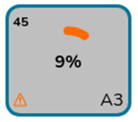
Spaces with a dispense in a LOADED state with "loadPercentage" less than “detectionThreshold” (Unfilled space)
Locker representation:
Blue border
Attention sign at the left bottom side
Detection threshold (upper left side) has the correct value (45)
Load percentage (centered) has the correct value (9%)
Circle around the percentage isa orange
Spaces with a dispense in a LOCKEDDOWN state with "loadPercentage" greater than or equal to “detectionThreshold” (Filled space)
Locker representation:
Dark red border
Check mark at the top right side
Detection threshold (upper left side)
Load percentage (centered)
Circle around the percentage is blue
Spaces with a dispense in a LOCKEDDOWN state with "loadPercentage" less than “detectionThreshold” (Unfilled space)
Locker representation
Dark red border
A dark red lock pad icon positioned at the top right corner
Detection threshold (upper left side)
Load percentage (centered)
Circle around the percentage is orange
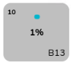
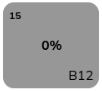
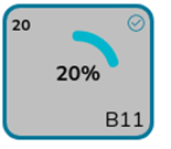
Spaces with no orders associated (available spaces with no orders in loaded or locked down status):
Available space with "loadPercentage" less than “detectionThreshold”
Applies to these cases:
Unfilled space but without dispenses associated
Unfilled space with dispenses associated in loading status
Locker representation:
No borders
No caution signs
Detection threshold (upper left side)
Load percentage (centered)
Circle around the percentage is blue
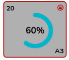
Space having a “loadPercentage" greater than or equal to “detectionThreshold”
Applies to these cases:
Filled space but without dispenses associated
Filled space with dispenses associated in loading status
Locker representation:
No border
Attention sign at the bottom left side
Detection threshold (upper left side)
Load percentage (centered)
Circle around the percentage is red
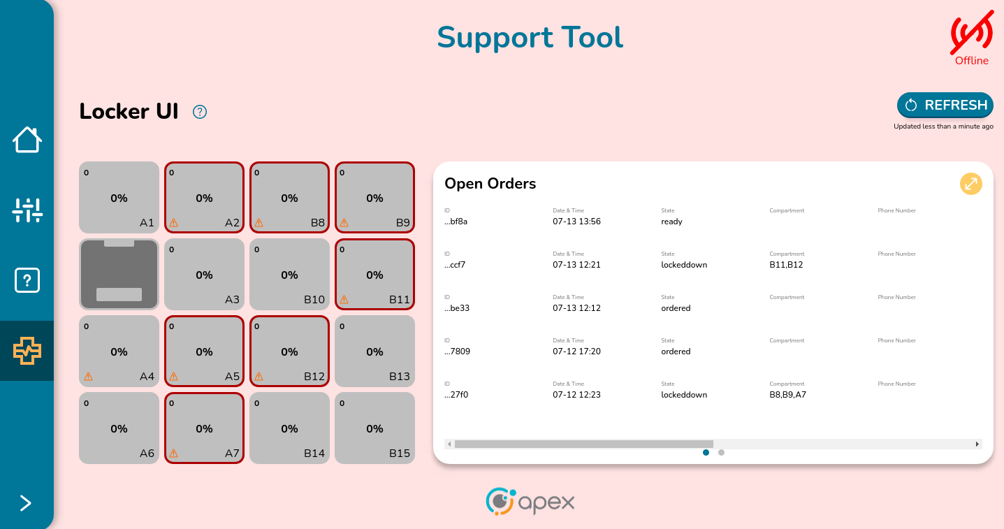
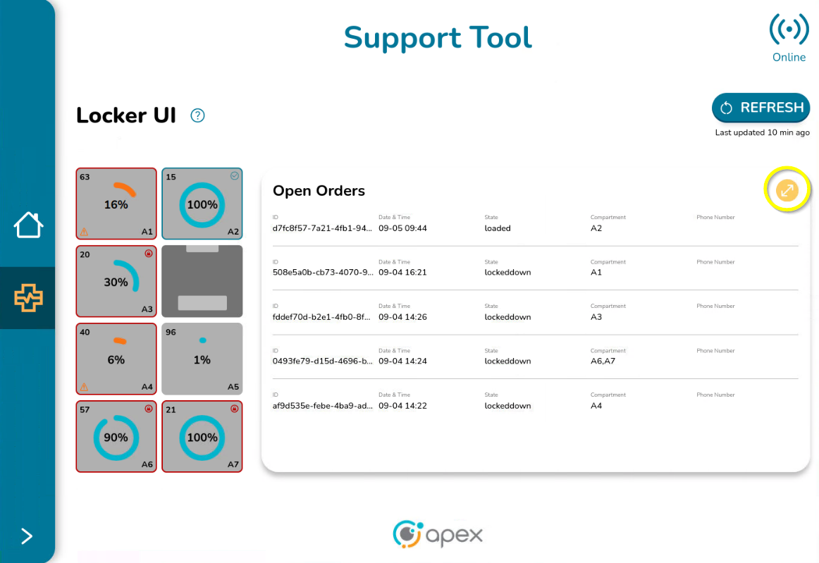
Open Orders Component
At the right side of the Locker UI screen, there is the Open Orders table which contains basic information related to each open order associated with the device:
ID - Unique identifier of the order. Due to the size of the table, only the first characters of the whole ID are displayed
Date and Time - The date and time in which the order was created
Status - The status of the dispenses associated with the order
Compartment - The label that identifies the position the order is occupying. If the order is not placed at any space, this information is empty
Phone Number - The phone number that was provided when the order was created. Not all orders are associated with a phone number so this field can be empty if that is the case.
The table presents 5 orders per page. If there are more than 5 orders, the user can swipe to the right to see the next set of orders or go back by swiping to the left. The number of dots at the bottom of the table indicate how many pages the table has. The blue dot indicates which page the user is on. The table contains a yellow button to expand the open orders information in a new screen.
Help Button Component
Right after the locker UI title, there is a question mark Icon:
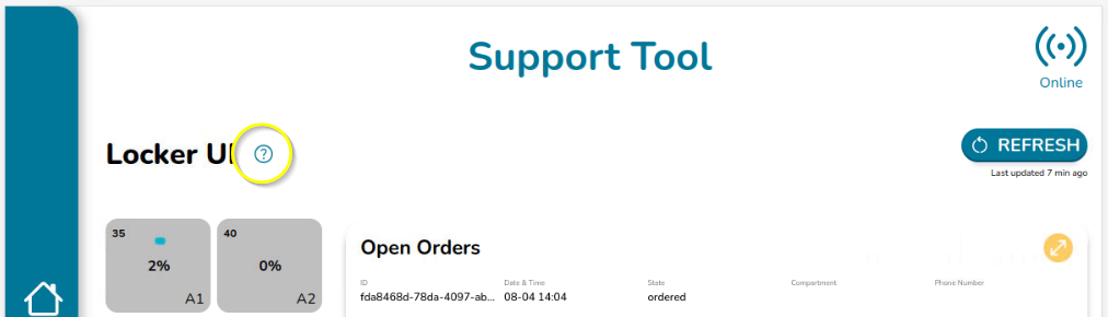
Clicking the question mark opens a popup on the right side that contains information explaining the colors and symbols used to represent the conditions of the lockers:
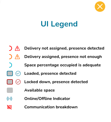
To close the UI Legend popup, click on either the close button or the help icon again.
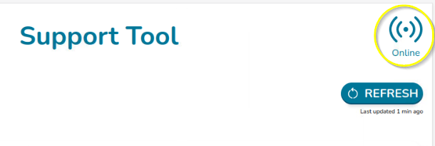
Online Indicator Component
The online icon is placed at the top right side of the screen. When the device is online, the indicator has the below appearance:
If the device is offline, the Support Tool Dashboard screen looks like the image below, indicating there is a problem with the connection and the Application cannot be used.
Refresh Button Component
The refresh button is at the top right of the Locker UI screen.
When clicking on the REFRESH button the following events happen:
If the locker's conditions have changed (i.e. locker's fill/unfill indicator has changed, new orders have been delivered to a locker or orders have been removed from the locker), each locker reflects the new changes.
If the Open orders have experienced any change (i.e. new orders have been created, orders have been delivered or orders have been dispensed/reclaimed from lockers), the new list of open orders is reflected in the table.
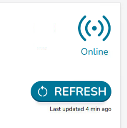
Right under the REFRESH button, the message “Updated less than a minute ago” is displayed.
This message is replaced every minute to inform the user of how many minutes have passed since the latest refresh with the message “Last updated <minutes_ago> min ago”. For example, if 4 minutes have passed since the latest refresh, the message “Last updated 4 min ago” is displayed.
If the device is offline, when clicking on the REFRESH button, the Support Tool Dashboard screen looks like in the image below, indicating there is a problem loading the lockers.
Open Orders Screen
To open the Open Orders screen, click on the yellow circle arrows button to expand the open orders table:
The Support Tool Open Orders screen opens the following:
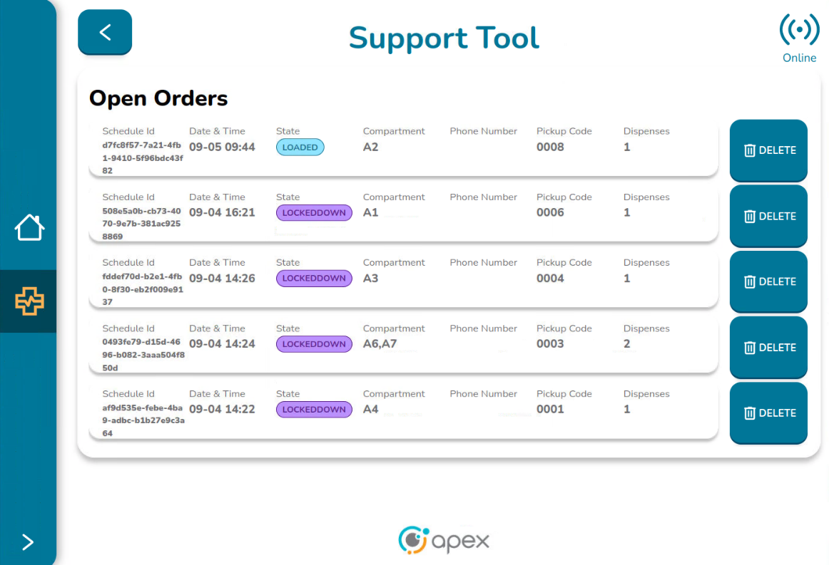
This screen contains the following elements:
Open Orders List - List of orders which are currently in Open status. This list must contain the same orders previously displayed on the Dashboard.
Delete Buttons - Delete button in front of each order
Online Icon - Indicates if the Support Tool is available
Back Button - Takes the user back to the Dashboard screen
Open Orders List
Below is some basic information related to each open order associated with the device:
ID - Same as the dashboard, this is the unique identifier of the order. The whole ID number is displayed here.
Date and Time - Same as the dashboard, this is the date and time in which the order was created
State - Same as the dashboard, this is the state of the dispenses associated with the order. The states are presented in colors to differentiate between the different states.
Compartment - Same as the dashboard, this is the label that identifies the position the order is occupying. If the order is not placed at any space, this information is empty
Phone Number - Same as the dashboard, this is the phone number provided when the order was created. Not all orders are associated with a phone number so this field can be empty if that is the case
Pickup Code - Code used to pick up the order
Dispenses - This is the number of dispenses associated with each order, meaning the number of spaces that the same order is occupying. Generally, this number varies between 1 and 2. If there are no issues, all dispenses must share the same status.
The screen presents 5 orders per page. If there are more than 5 orders, the user can swipe to the right or the left to see the next set of orders or go back swiping to the left. The number of dots at the bottom of the table indicate how many pages the table has. The dot coloured blue indicates in which page the user is placed.
Deleting an Order
To delete an open order, regardless of the status, click on the DELETE button placed in front of the order that you want to delete:
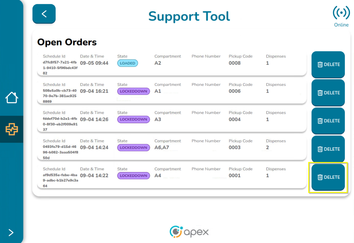
The Application Tool displays a delete warning screen which contains the following elements:
Warning Message - “Are you sure you want to delete the order <orderID>? The user can always go back by canceling the process
Cancel Button - Cancels deleting the order
Delete Button - Deletes the order
Back button - Goes back to the Dashboard screen
Online Icon - Indicates if the Support Tool is available
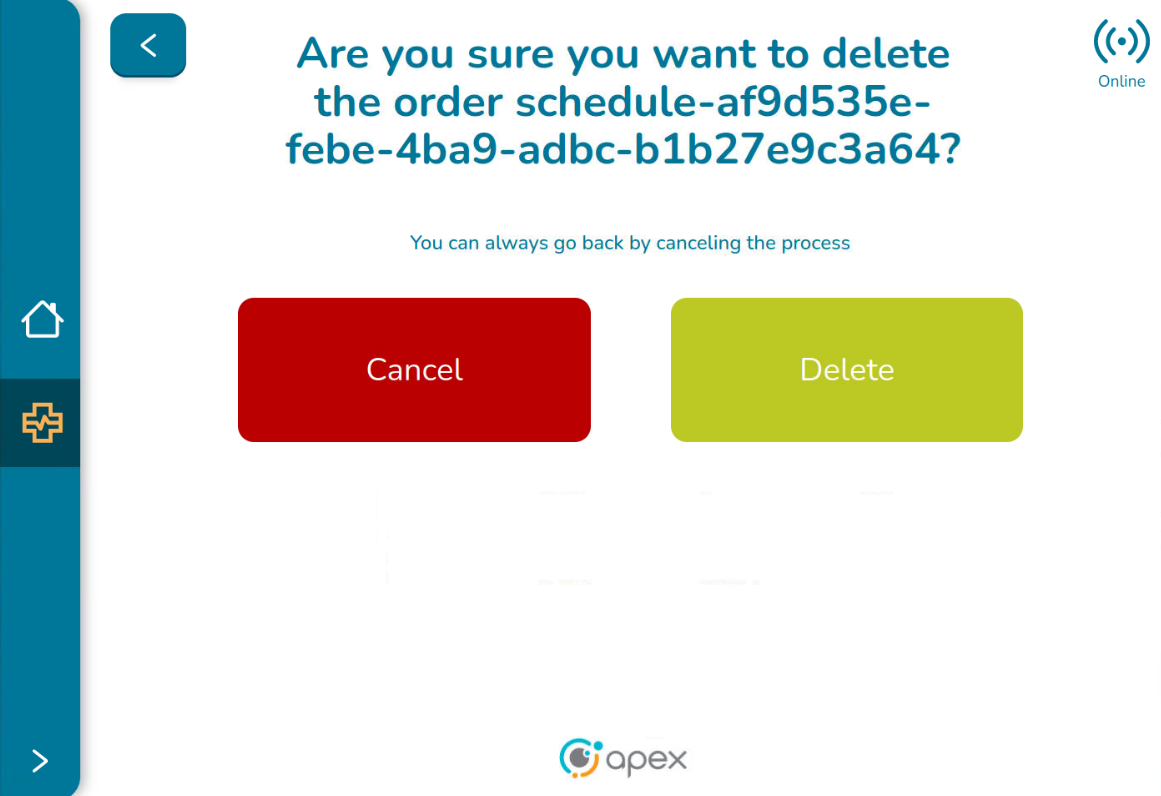
Canceling a Delete Order
To cancel the order deletion, click either the Cancel button or the back button. The application tool is redirected back to the Support Tool Open Orders screen and no changes are applied to the table. The user stays in the page where the order was selected.

Clicking on the back button, the Support Tool Dashboard screen is displayed again with no changes.
Delete an Order
To delete an order, click on the Delete button. The following will occur:
While deleting, a momentary “deleting order” message is displayed
After deletion, the message “Order deleted” is displayed. Click on dismiss to close this message or wait a few seconds until it vanishes.
After deletion, the Support Tool Open Orders screen is displayed again and the list of orders is updated accordingly
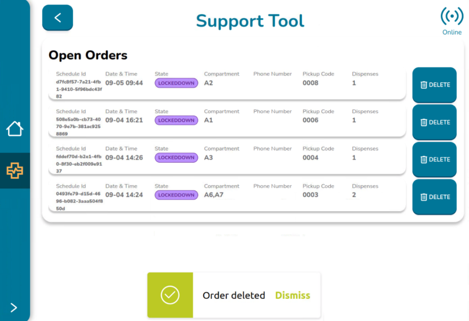
Clicking on the back button, the Support Tool Dashboard screen is displayed again. The list of orders is displayed accordingly without displaying the removed orders. If a locker occupying one space was removed, the space is updated so that it has the appearance of an available space.

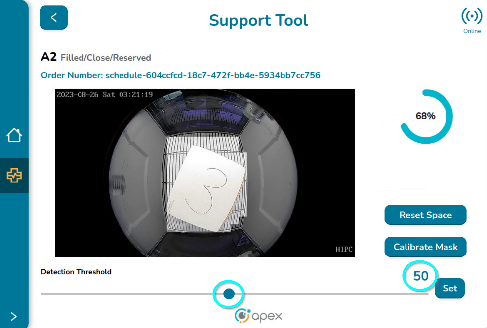
Space Details Screen
To open the Space Details screen (no matter if it is enabled or disabled), double click on a specific space:
The Support Tool Space details screen opens:
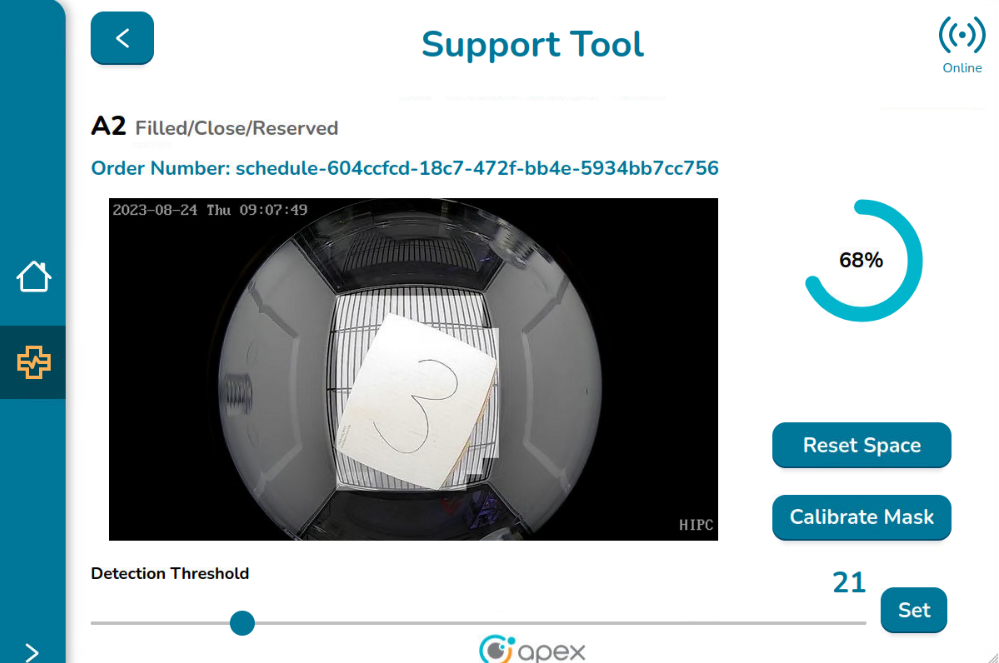
Online Icon - Indicates if the Support Tool is available
Space Label and its Current Status - The label of the selected space is displayed along with its current status which is taken from the ApexIQ Edge Data Store:
The first value is for “presence”. It could be filled or unfilled to indicate if the space has an item inside or not.
The second value is for “secure”. It could be closed or open to indicate the door status.
The third value is for “selectable”. It could be available or reserved. If reserved, the locker is occupied with an order. If available, the space can be used to load an item. It could also be disabled in the case where a space is disabled.
Space Image - Each space has a camera so that the user can see what is inside the space.
Load Percentage - As a reminder for the user, the load percentage of the space is displayed again on this screen. The completeness circle on this screen is always displayed in blue regardless of the color displayed in the Locker UI screen.
Resetting a Space
Reset an enabled space with no order associated:
When clicking on the Reset Space button for enabled spaces where no orders are delivered, the following events happen:
The space status changes with the following values:
Presence: unfilled
Secure: close
Selectable: available
The message “Space reset successfully” is displayed. Click on Dismiss to close this message or wait a few seconds until it vanishes
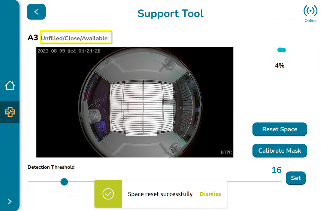
Clicking on the back button shows the Dashboard and the space will display the correct appearance, in accordance with the new values.
Reset a enabled space with order associated in statuses other than lockeddown or loaded:
When clicking on the Reset Space button, for enabled spaces where an order is delivered and the status of the dispense is something other than lockeddown or loaded, (for example a status of loading) the following events happen:
The schedule is deleted
The space status changes with the following values:
Presence: unfilled
Secure: close
Selectable: available
The message “Space reset successfully” is displayed. Click on Dismiss to close this message or wait a few seconds until it vanishes.
For those devices with lights, as the space is already reset, its color is changed to the one configured in the absentCompartment property (which is usually magenta).
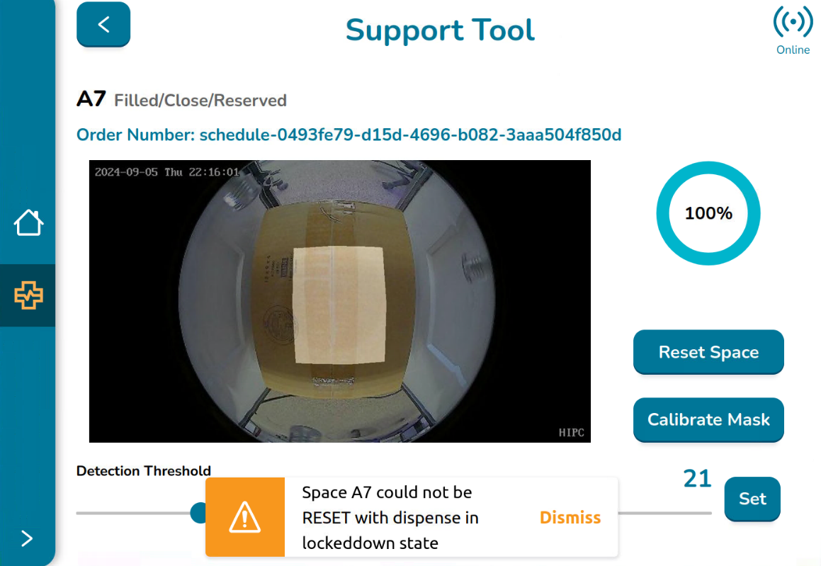
Reset a enabled space with order associated (lockeddown or loaded):
When clicking on the Reset Space button, for enabled spaces where an order is delivered and the status of the dispense is lockeddown or loaded, the following events happen:
The space status cannot be changed
For orders in loaded state, the message “Space <space> could not be RESET with dispense in loaded state” is displayed. Click on Dismiss to close this message or wait a few seconds until it vanishes.
For orders in lockeddown state, the message “Space <space> could not be RESET with dispense in lockeddown state” is displayed. Click on Dismiss to close this message or wait a few seconds until it vanishes.
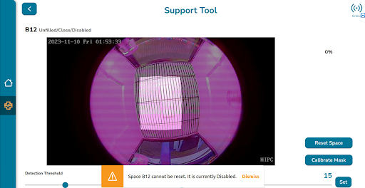
Reset a disabled space:
When clicking on the Reset Space button, for disabled spaces, the following events happen:
The space cannot be reset.
The message “Space <space> cannot be reset. It is currently Disabled” is displayed. Click on Dismiss to close this message or wait a few seconds until it vanishes.
Calibrating the Mask
The mask is the area detected by the camera that is used to define the percentage occupied by an item placed in the space.
When clicking on the Calibrate Mask button, an internal process runs to calibrate the value of the variable MIN_RATIO. The message “Mask calibrated successfully” is displayed. Click on Dismiss to close this message or wait a few seconds until it vanishes.

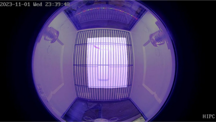
The user can see how the mask changes when the mask is calibrated, as the example in the images below:
Before calibrating the mask
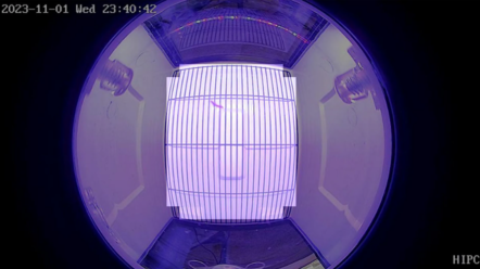
After calibrating the mask
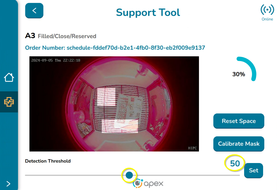
Updating the Detection Threshold
The Detection Threshold can be updated. The minimum value accepted is 3 and the maximum value accepted is 100. It only accepts integer values. To change the threshold, just move the slider to the left to decrease, or to the right to increase the value. The current value will be displayed next to the set button.
When selecting the value, click on the Set button and the following events happen:
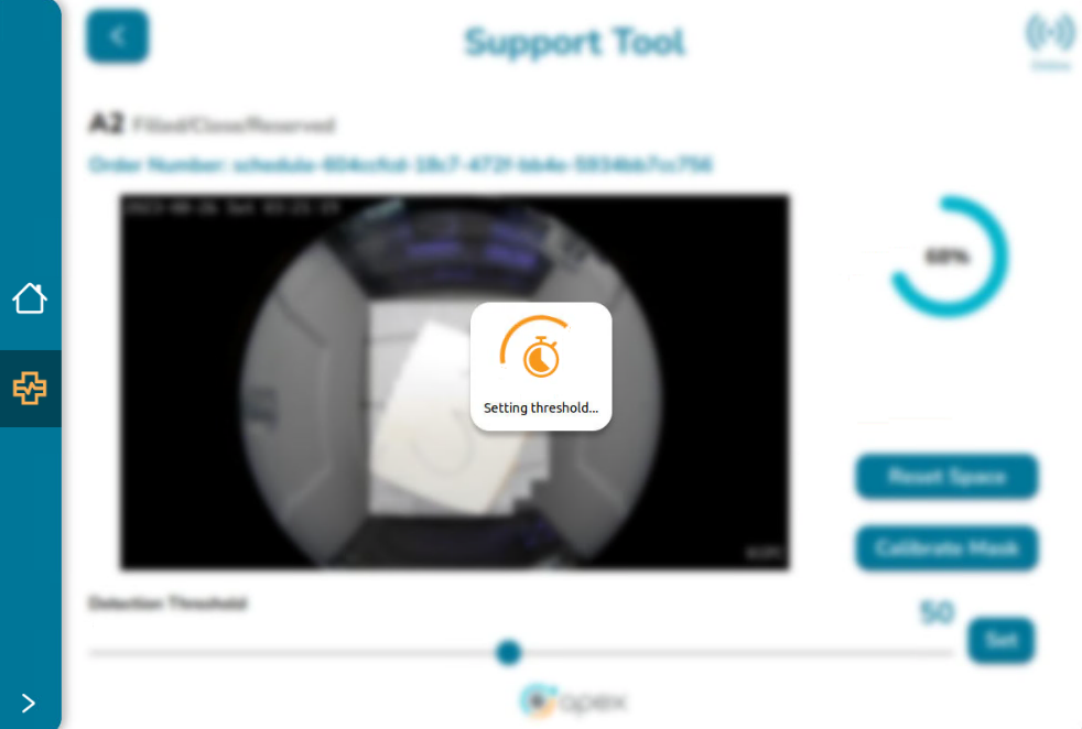
The message “Setting Threshold…” is displayed and the background is momentarily disabled.
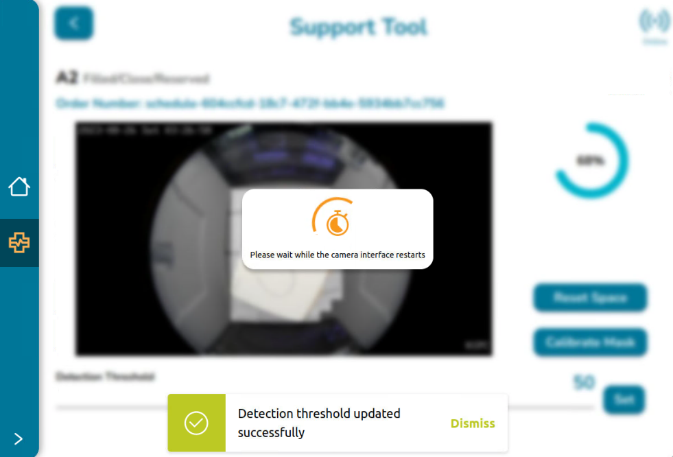
After a few seconds, the message “Detection threshold updated successfully” is displayed. Click on Dismiss to close this message or wait a few seconds until it vanishes.
Also, the message “Please wait while the camera interface restarts” is displayed. This happens because the system takes some time to reestablish the service so the camera is not available during that time.
After the service is reestablished, the screen is enabled again (and displays the new value) to continue interacting with the application.
When returning to the Locker UI screen, the updated threshold is reflected for the selected space. The completeness circle may change its appearance based on the new relationship between the detection threshold and the percentage of space occupied by the object.
Key Reminders
If the load percentage is greater than or equal to the detection threshold, the space is considered filled.
If the load percentage is lower than the detection threshold, the space is considered unfilled
Example:
Before updating the threshold, the space had a detection threshold of 20. With a load percentage of 30, the space was considered filled since the load percentage was greater than or equal to the threshold.
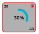
After updating the threshold to 50, with the same load percentage of 30, the space is now considered unfilled because the load percentage is below the new threshold. As a result, the completeness circle changes to orange, and an attention sign appears at the bottom left, indicating an inconsistency or something that needs to be fixed.
Logging out of the Application
Once the user is logged into the application, there is not a logout button, and as mentioned in the login section, the session will be alive for 15 minutes with the option of extending the session.
In order to leave the Application Tool before 15 minutes or at any time, the user must click on the Home button located in the left main menu.
The home button will redirect the user to the Associate UI setup page. From there, the user can hit the Home button again, which will redirect the user to the default context in the device.
TeamViewer, SAM and Interim V3 Field Support
The VA/DEV team currently uses TeamViewer to remotely access and control the NUC that resides within the early V3 devices in the field. What follows is the documentation for how to utilize TeamViewer to obtain device information ranging from connectivity status to camera status, etc.
The reason why this is termed an ‘interim’ approach is because TV is only required prior to V3 devices being fully peer’d (Cloud and Local peers). The ‘Cloud Peer’ feature isn’t yet into production but once it is and the cloud-local protocol is complete, TV will no longer be necessary to obtain device telemetry. This is anticipated to happen in 2023. Until that officially happens and is communicated to the business, TV will continue to be used.
Note
While TV doesn’t have a restriction on ‘seats’ it does only allow 3 open ‘channels’ at a time, so care needs to be taken when TV is being used outside of VA/DEV since the VA SE’s and Developers need to use it when performing production support or system analysis.
The primary goal of TV + SAM usage is to understand current state of a device and its associated orders. There are a few small actions that a user can take to rectify certain issues but largely the TV/SAM combination will allow a TSA to best understand the state of the device, the state of an order, the view through the space’s camera and whether or not what is being experienced is a system issue or user error.
The first steps to accessing and using this interim support are as follows:
Download the applicable OS TeamViewer application at https://www.teamviewer.com/en-us/download/windows/ and complete the application setup.
Obtain a set of credentials by emailing Anders Cool at anders.cook@apexsupplychain.com or Dave Doster at dave.doster@apexsupplychain.com
Upon receiving credentials, log in to the TeamViewer application to access the dashboard.
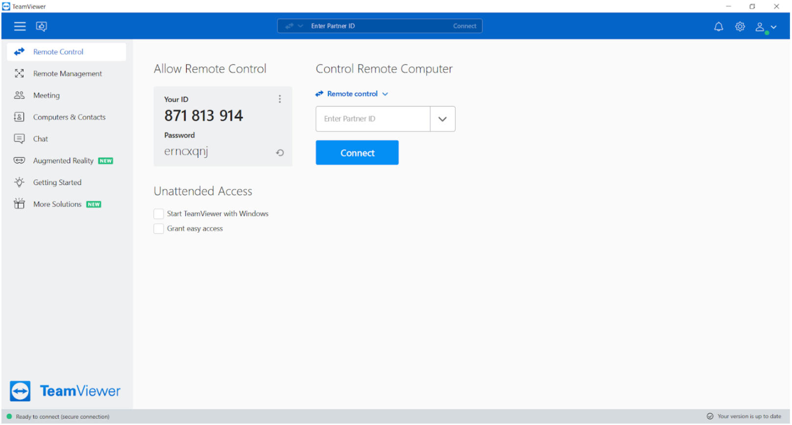
From the dashboard, navigate to the “Computers and Contacts” tab on the left-hand side the user will see the following:
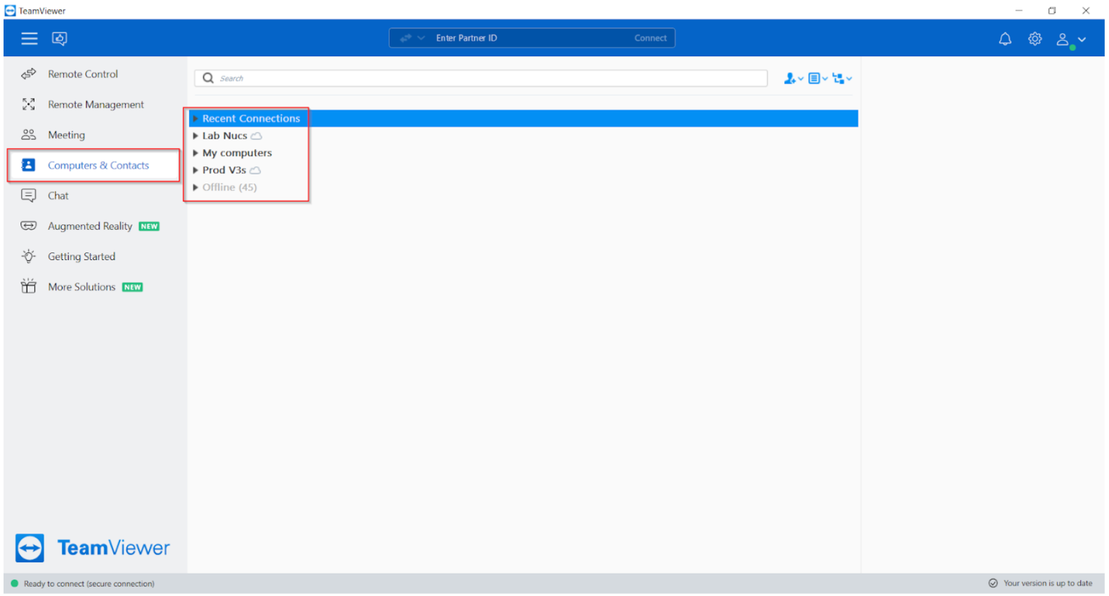
From the Computers and Contacts tab, the user will see a list of “Lab NUCs”, “My Computers”, “Prod V3’s” and “Offline”. The primary interest will be with “Lab NUCS” for testing devices and “Prod V3’s” for insight into V3 devices that are in the field.
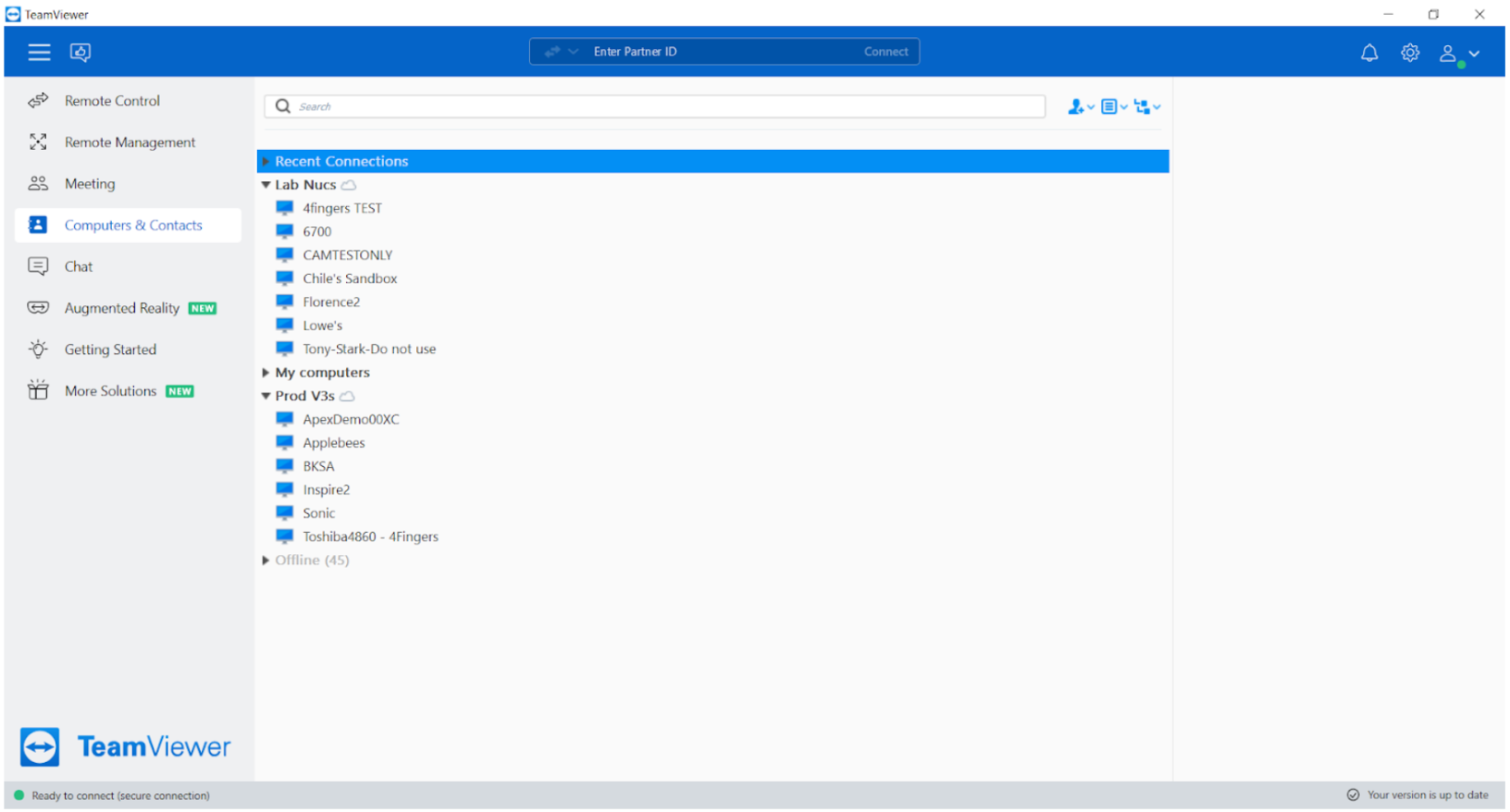
From the expanded sections the user will see the individual devices (NUCs) for insight into. To select a NUC place the cursor over the desired target and double click.
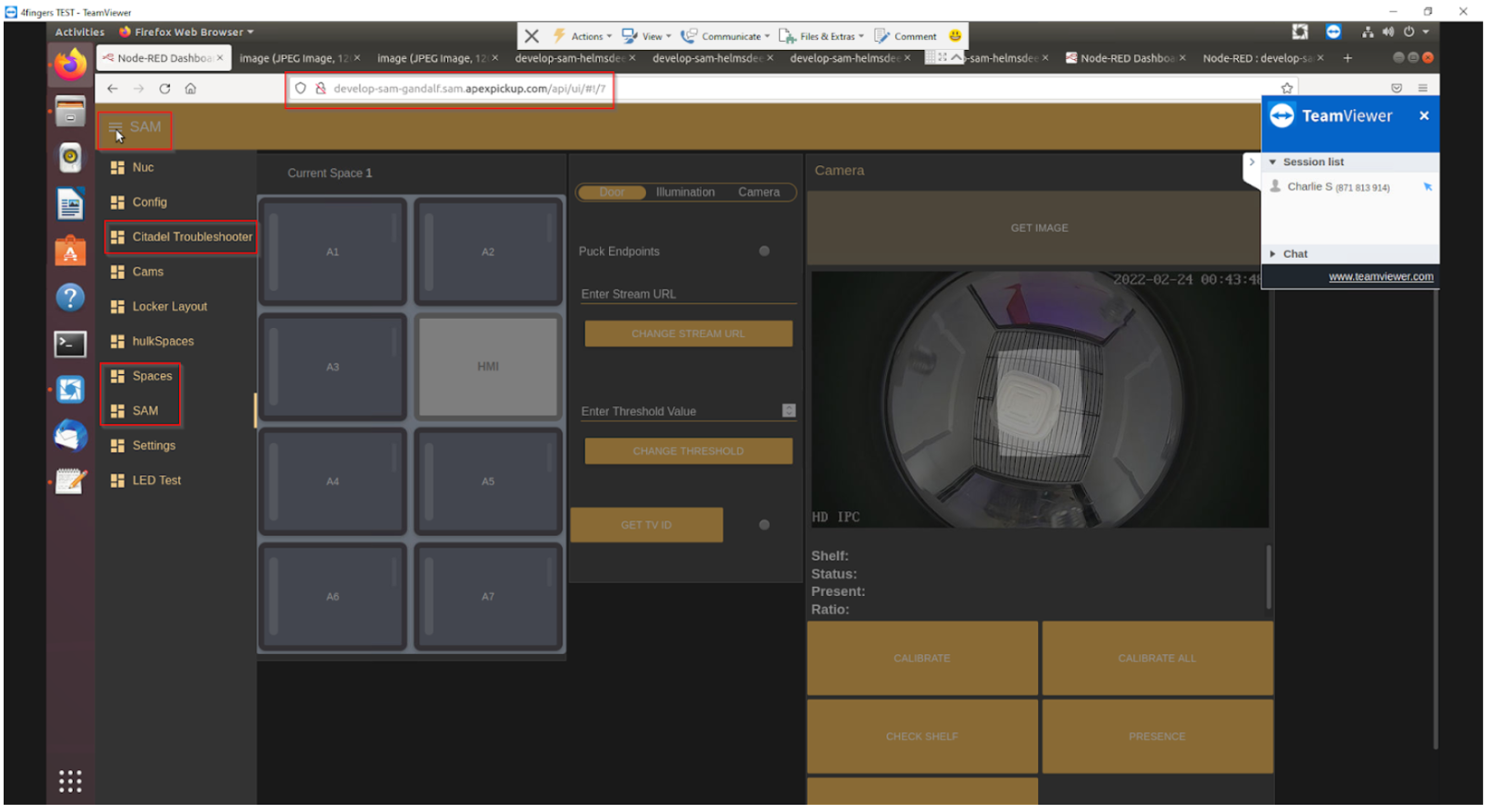
Upon double clicking the desired target device, the user should automatically route into the NUC for that device. From here, the user will access the SAM tool that resides on the NUC by inputting the NUC URL in a browser tab.
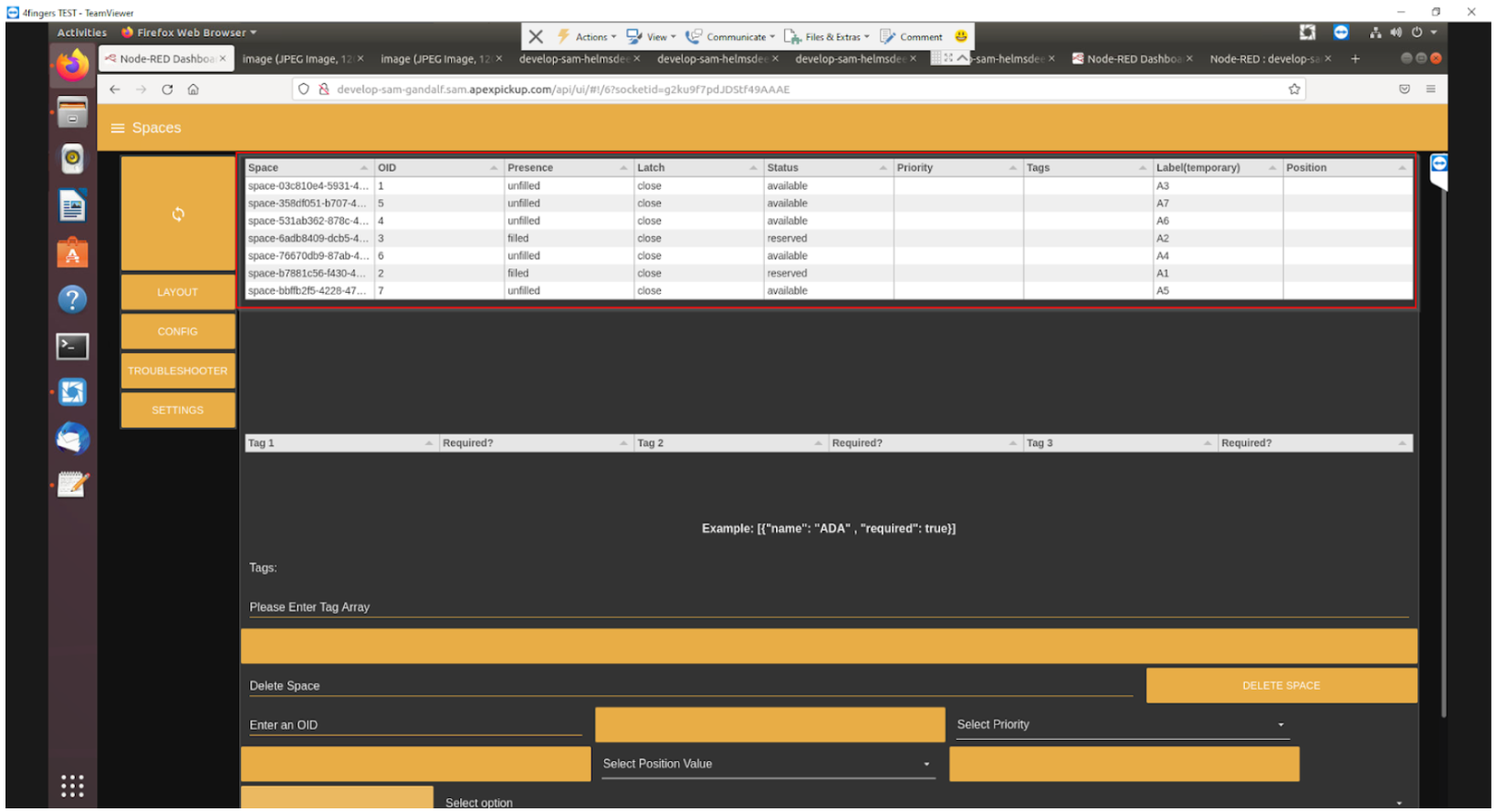
From the SAM URL, the user can access three sections of SAM that are critical to AIQ Support, which are as follows: Citadel Troubleshooting, Spaces and SAM.
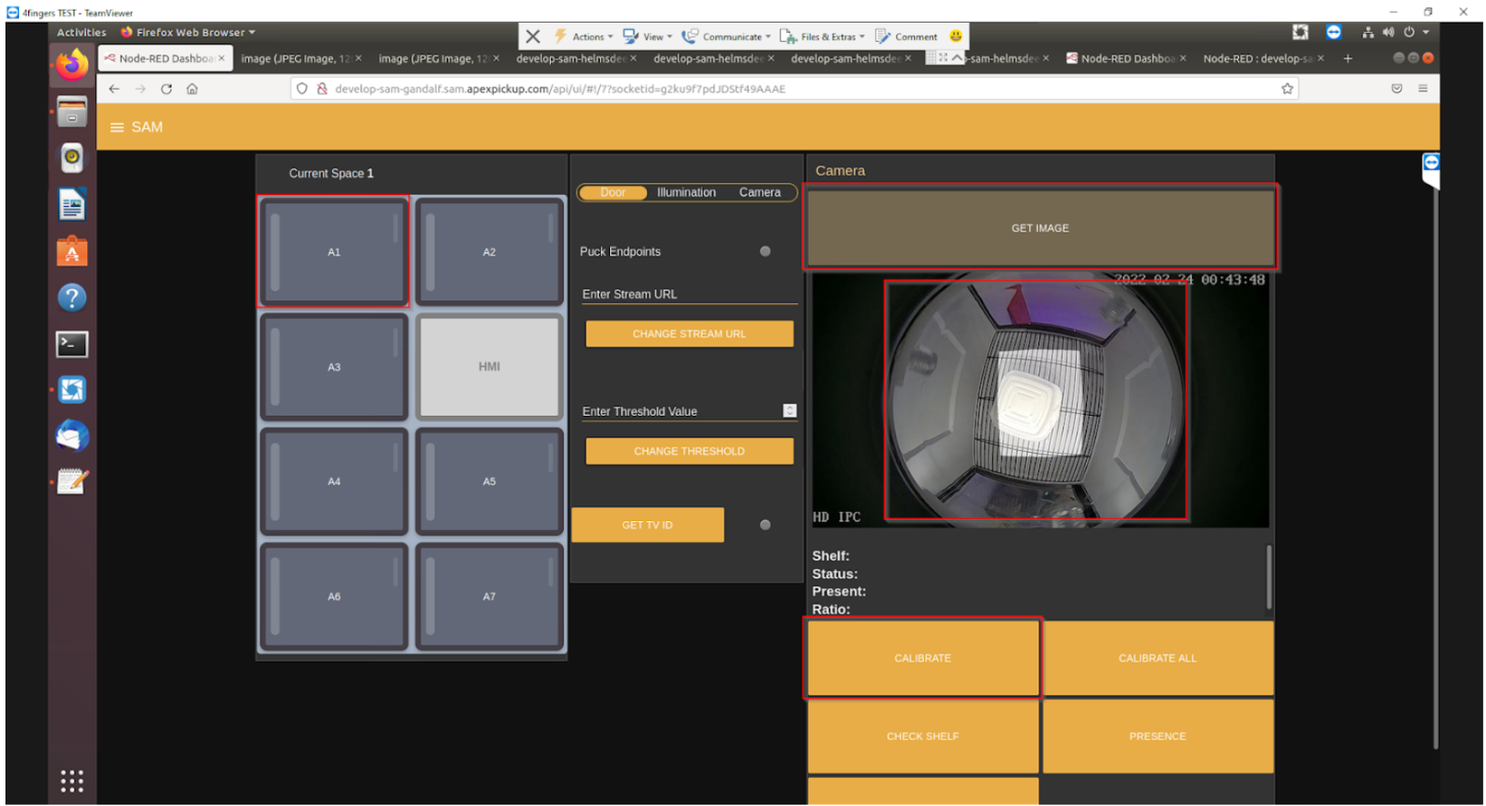
The SAM tab is the primary use tab and should be used the most for general positional and camera insights. This can primarily be achieved by selecting a position and clicking the “Get Image” button. This should render the view that the camera saw at the moment of request as well as show the viewer what the camera mask is set at (the white box/shape). Additionally, from this screen, if a camera appears to be incorrectly calibrated, the user can re-calibrate a position’s camera via the ‘calibrate’ button.
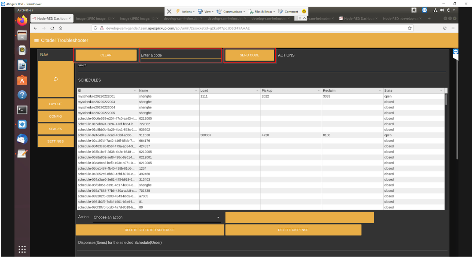
The Citadel Troubleshooting tab is primarily used for querying orders that are related to that specific device, specifically by code. This provides insight into the following: schedule id, name, load code, pickup code, reclaim code and current state of the schedule.
The Spaces tab is primarily a validation tab, that what is seen on the SAM and Citadel Troubleshooting tabs is reflected by the Space’s status, as well as displaying Space name, Space ID, Presence status, latch status along with a few additional data points that are not yet relevant.
EOL - Network and Ordering Configuration - Associate UI
Outlined below are the procedures for network and ordering configuration. As the product evolves and matures, these screens and procedures will be updated accordingly.
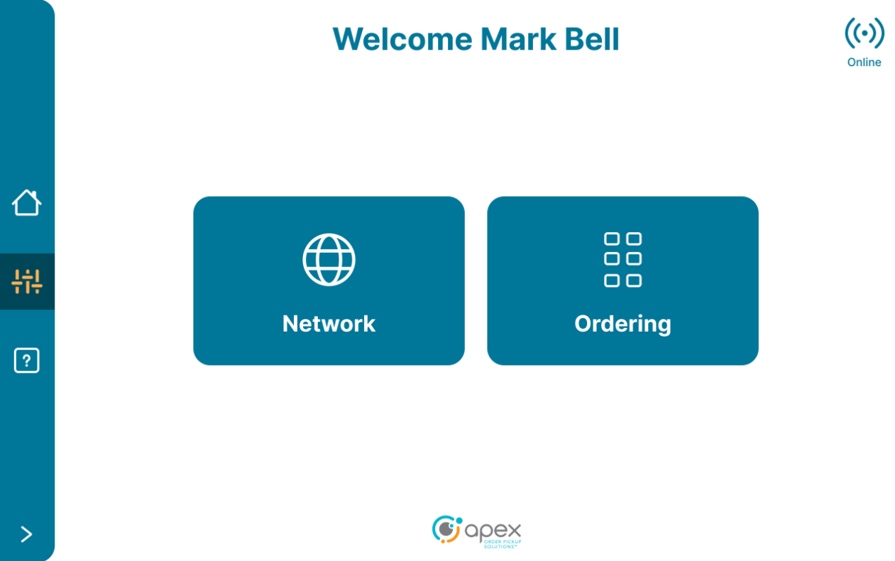
Users will start out on the Welcome screen. Open the left side menu to bring up the setup button.
Press the setup button.
The service password button will be displayed. The user will take note of this password as it is used on the next screen. To proceed, press the service password button.
Enter the service password to proceed to the Network and Ordering selection screen.

Select the desired setup process to proceed with configuration for Network or Ordering + Activation.
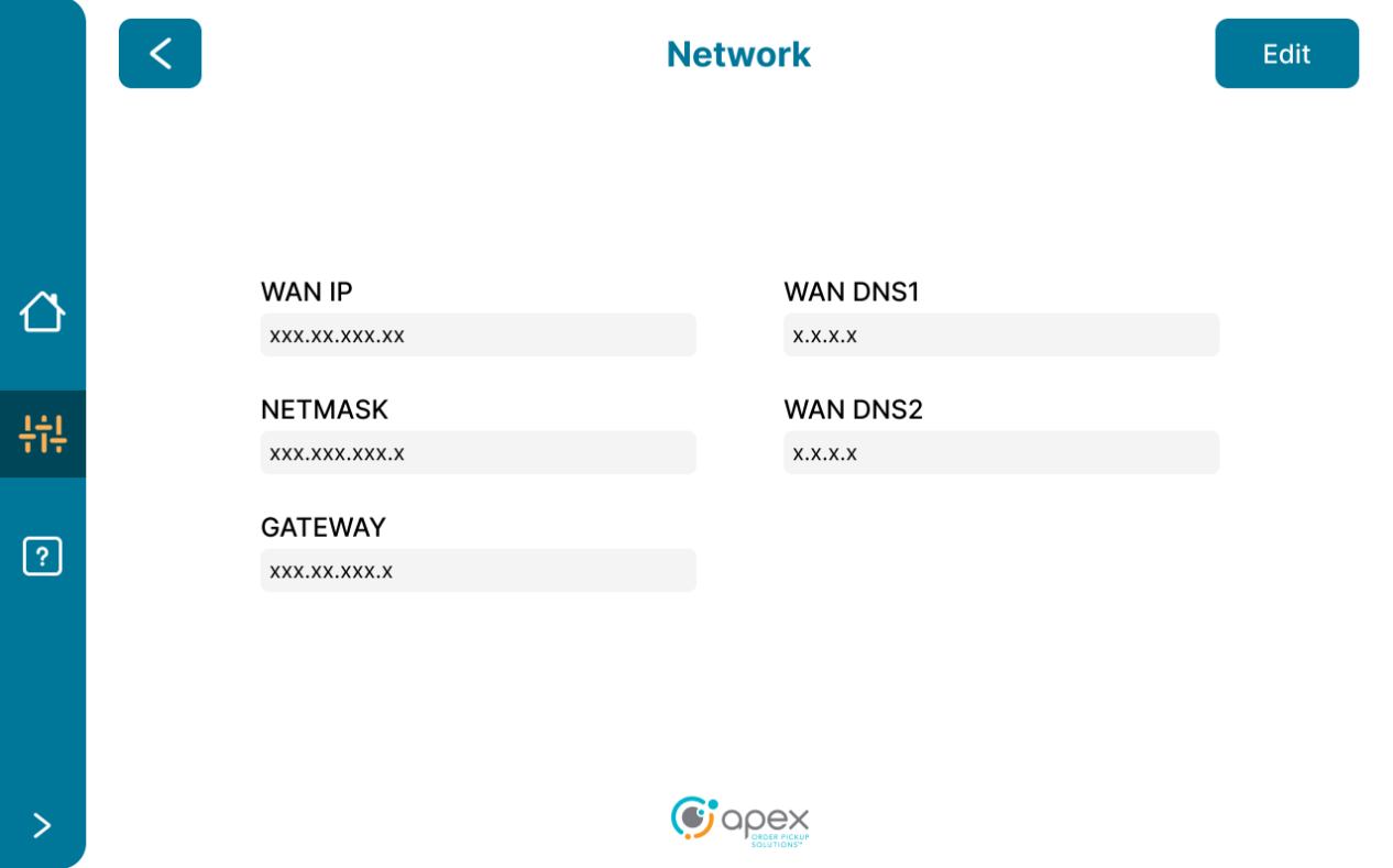
Network
After selecting Network, users are shown the Network screen with fields for:
WAN IP
WAN DNS1
NETMASK
WAN DNS2
GATEWAY
Select the edit button to make changes to the information in these fields.
After making the desired changes, select the save button to save the changes.
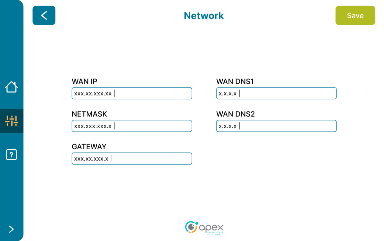
Press the left arrow back button to return to the Network and Ordering + Activation selection screen.
Ordering and Activation
After selecting Ordering, users are shown the Device Ordering screen.
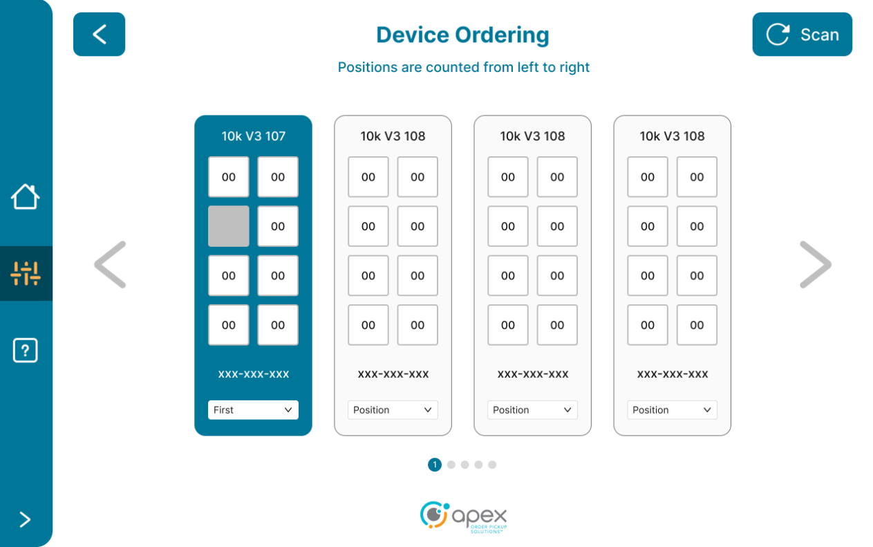
Users select from the dropdowns the positions of each device from left to right. Select the Scan button to refresh the device list if needed.
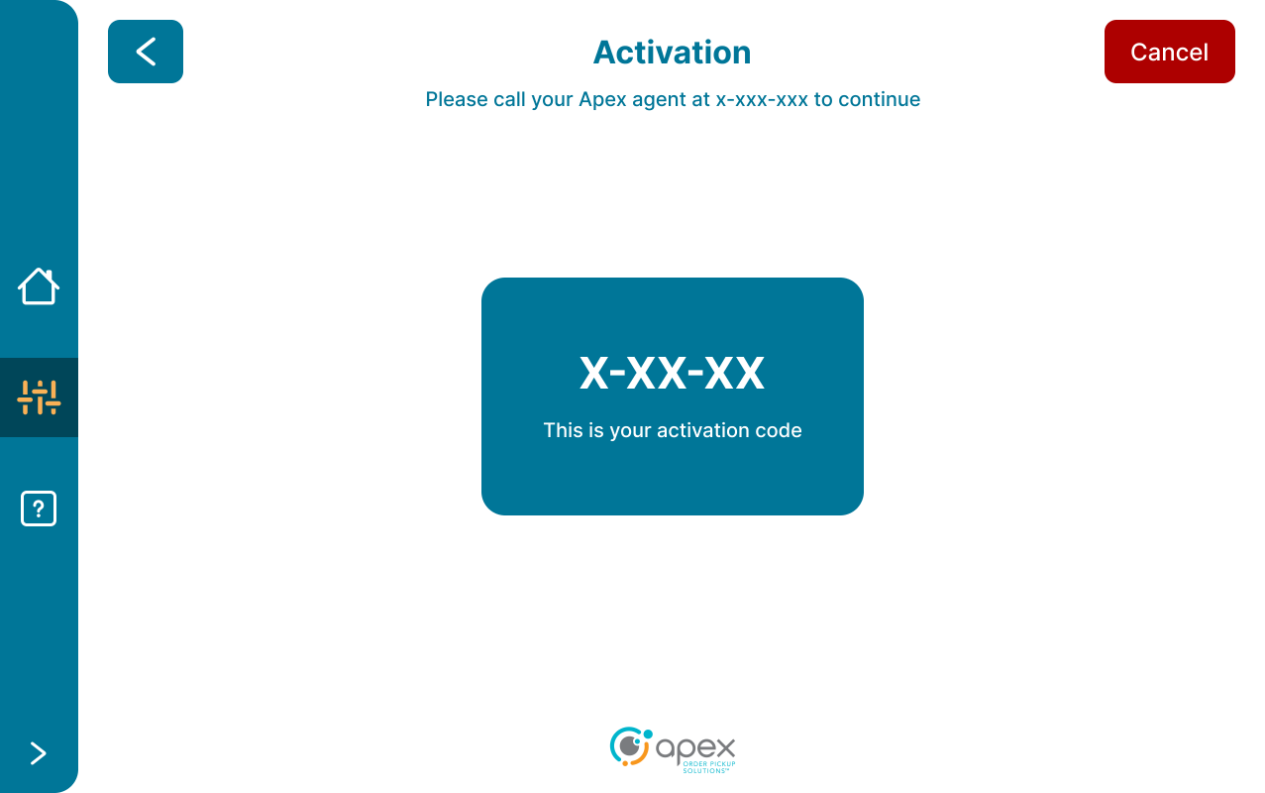
After configuring the desired positions, select the Activate button to proceed with device activation.
Users are shown the Activation screen which displays the activation code and the number for their Apex agent. To proceed with the activation process, note the activation code and call the number for the Apex agent.
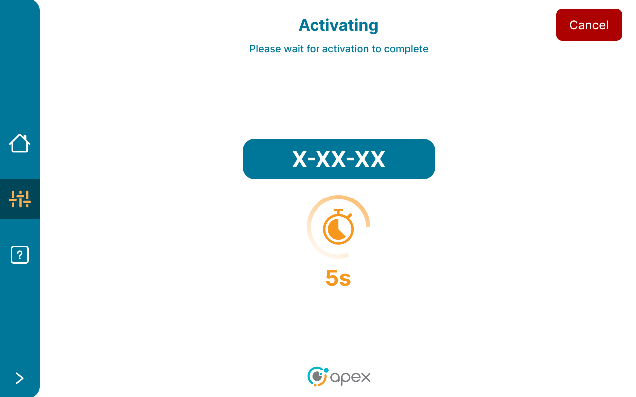
Once activation is in progress, users are shown the Activating screen with a countdown timer.
Portal User Guide
Introduction
The AIQ Portal is the primary user interface for any Apex, Customer or 3rd Party actor who wants to perform Account Management, System Configuration & Management, User Management and Reporting on an Apex Account, Site or Device that is being managed by Apex Order IQ. What follows is a user guide for the AIQ Portal which is intended to outline the navigation, utilization and functionality of the application.
Workspaces & Hierarchy
Just like Trajectory had Owner Company, User Company, Site & Device and Lunar Journey had Account, Client, Location & POU, AIQ has its own hierarchy, which is fundamentally Account, Site & Device. What makes the AIQ approach to entities unique is that users can think of the hierarchal entities as layers of workspaces, which can be interacted with individually or as groups. Understandably this is a tricky concept to grasp, but the net-net is that it allows Apex the benefit of being more flexible as Accounts are constructed and need to perform advanced account & relationship management.
An example would be this: Often in Lunar Journey, decides had to be made between making the Account either the Customer or the Integration partner, since the LJ account type determined the access that the users of that account had to the Lunar Journey APIs. With AIQ, an Account can remain tied to a brand and sites can be created as individual but can also be bundled together in configurable ‘site groups’ so that reporting and integration management or even integration partner data access can be limited and managed without the hierarchy of an Account needing to be changed.
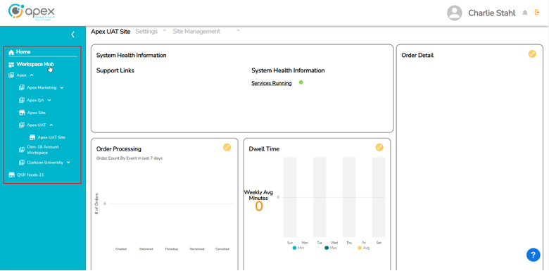
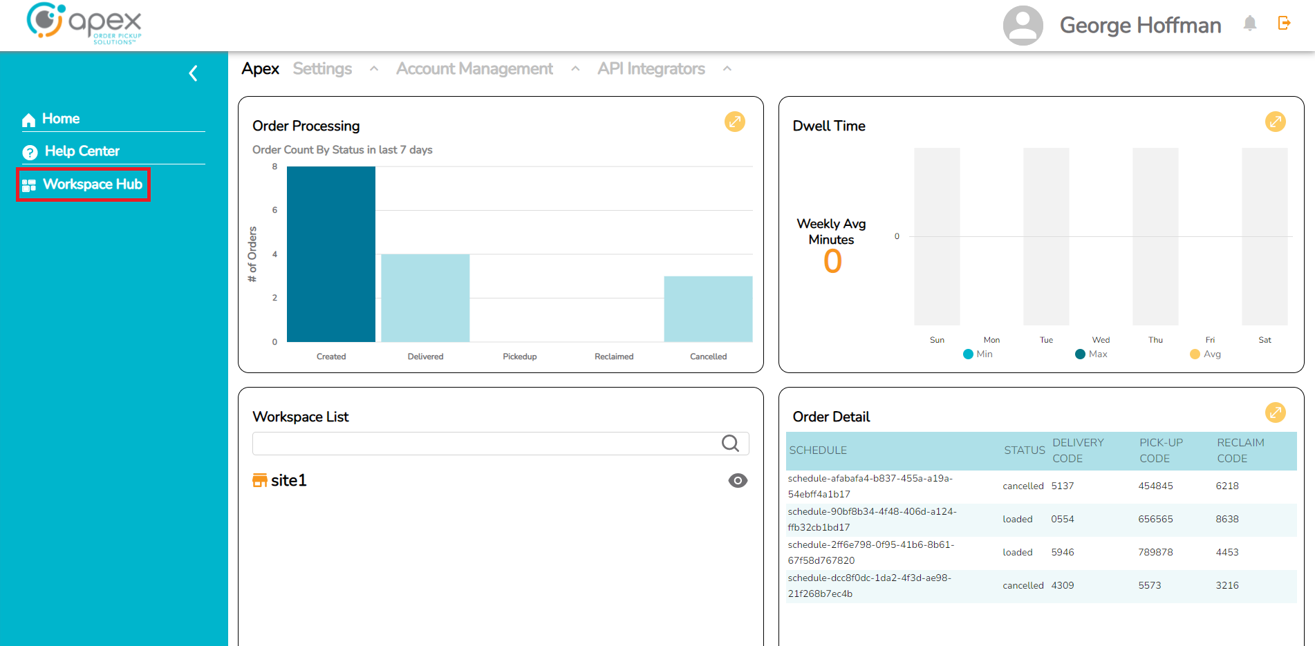
Workspace Hub Navigation
The navigation bar in general works by expanding + collapsing and the Workspace Hub portion behaves in a similar fashion. To expand the Workspace Hub the user clicks on the “Workspace Hub” wording in the navigation bar. To expand a specific Account to see its Sites, the user clicks on the Account they want to expand. To expand a specific Site to see its Devices, the user clicks on the Site they want to expand.
Any expanded selection will remain expanded until the user either collapses them (via the expand/collapse arrow next to the Account or Site name) or logs out of the application.
The Site level has a different default reporting schema than the Hub and Account levels and is primarily related to the importance of seeing system health by Site & Device.
Apex users will see all Accounts and have access to all Sites and Devices under those Accounts. Customer users will only see their own Account and the Sites and Devices thereunder.
Access
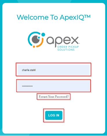
Upon navigating to the AIQ URL @ https://www.uat-keycloak.stg.apexpickup.com, users will land on the log-in screen for the AIQ Portal Application. On this screen will be the following fields:
Username field
Password field
Log in button
“Forgot Your Password?” password recovery link
Credentials
Apex User – for an Apex user to receive credentials, an access ticket will need to be created by product development on behalf of the user and issued to Shenghe Zhan. This is an interim process until full User Management is complete within the AIQ Portal, at which point an Apex user will be able to create other Apex users without assistance from product development.
This process will result in the creation of a username and a temporary password to the end user. This will then need to be replaced with a permanent password.
External User – For an external user to receive credentials, we will need to wait until full User Management is complete within the AIQ Portal. What we’re trying to avoid is giving premature access to this application before it is fully functional.
This process will result in the creation of a username and a temporary password to the end user. This will then need to be replaced with a permanent password.
Password Reset - If an AIQ Portal User needs to reset their password they will click the “Forgot Your Password?” link and following will happen:
User will be asked to supply email address associated with the Username.

If it is a registered email address, an Email will be sent to that email address with a link to reset the password.
The user will click the link and is taken to the AIQ Portal Reset Password Page.
The user enters a new password.
If the new password complies with the currently adopted security standards, it will be accepted and the user is granted access into the AIQ Portal application.
Password Security Standards Requirements:
Minimum of 8 characters
At least 1 upper case letter
At least 1 lower case letter
At least 1 special character
At least 1 number
Cannot be the same as the username
Cannot be a duplicate of the last 5 passwords used
Navigation
Upon successfully logging into the AIQ Portal, users will see the following landing screen.
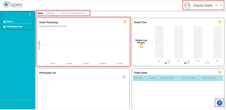
Currently the landing screen for the application is the Reporting Module. However, the navigation panel on the left-hand side of the page allows users to navigate across all of the hierarchies in the application. Items of note on the landing screen are as follows:
Username, Notifications Bell & User Logout on the page header.
Navigation Panel with a home button and an expandable/collapsible Workspace Hub button.
Hierarchy, Settings & Account Management buttons on the main UI header.
Reporting Widgets occupying the primary UI portion of the page.
Help Button in the form of a blue “?” bubble on the bottom right of the page. (NOT YET IMPLEMENTED)
Enable Custom Integration
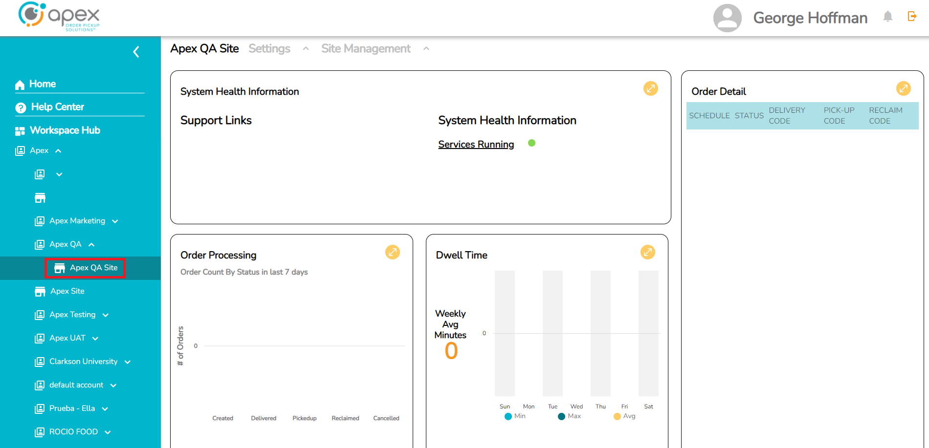
Click the workspace dropdown menu.
Click the down arrow next to the company (Apex in this example).
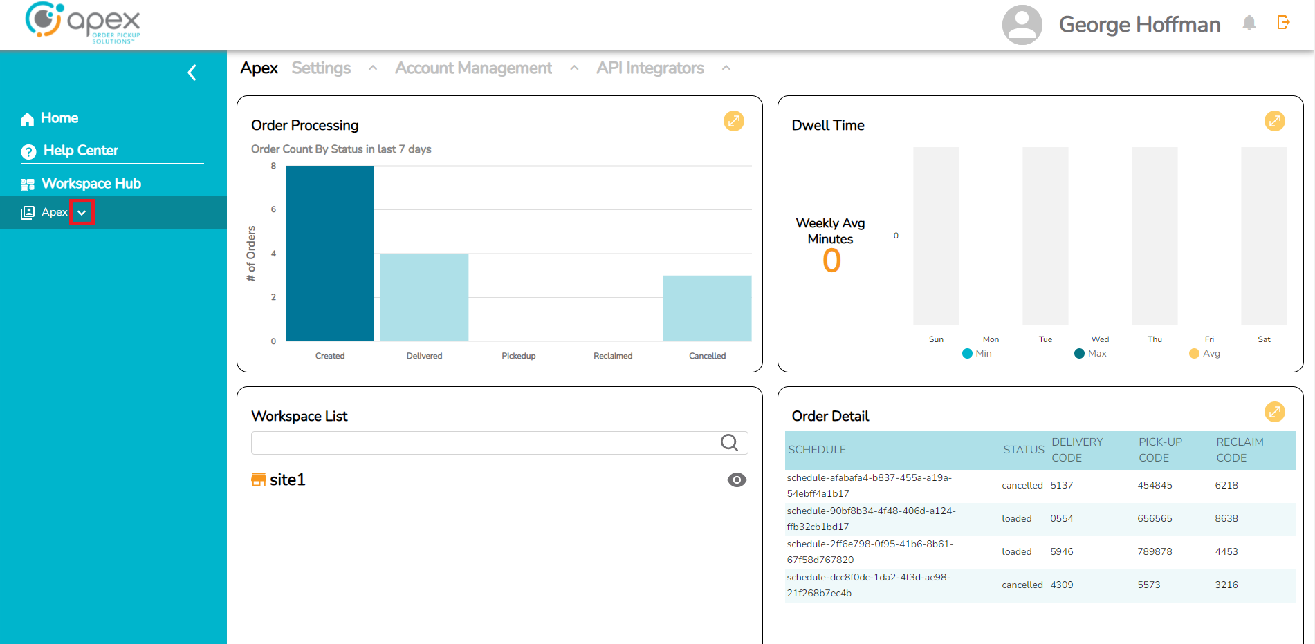
Click the desired account (Apex QA in this example).
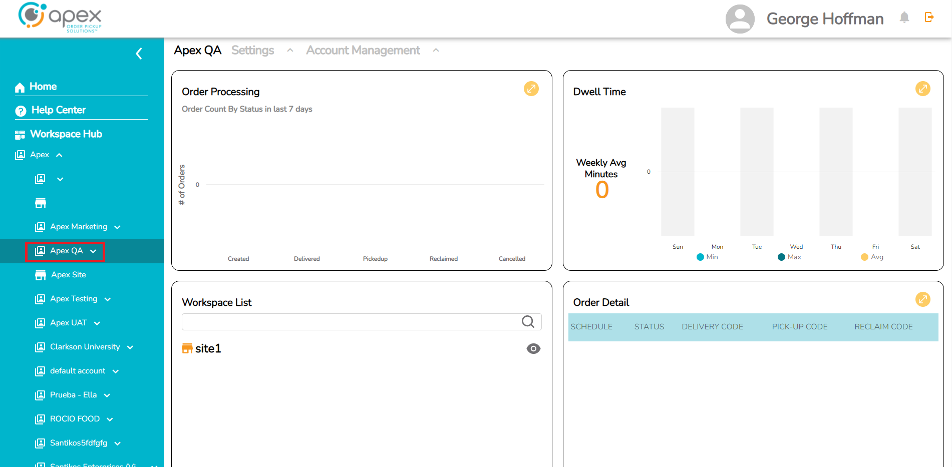
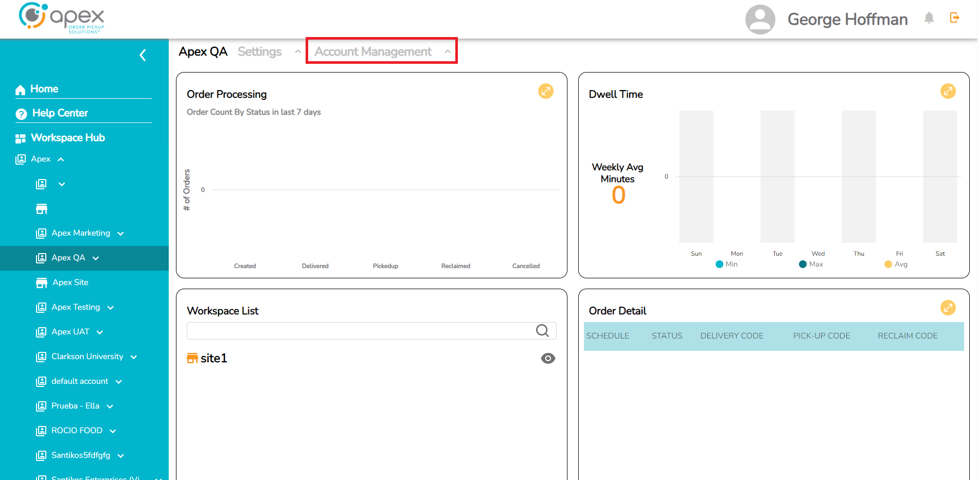
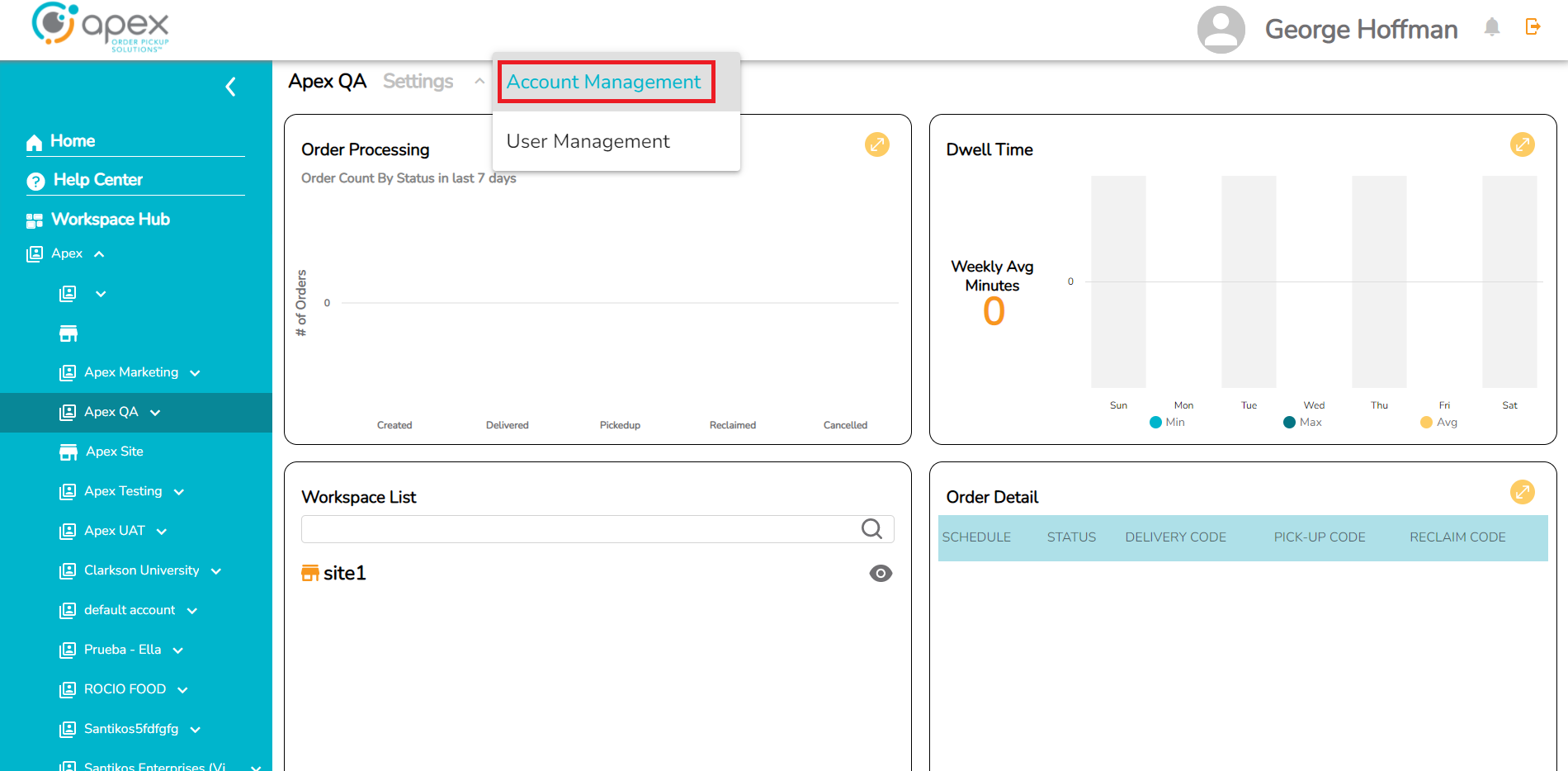
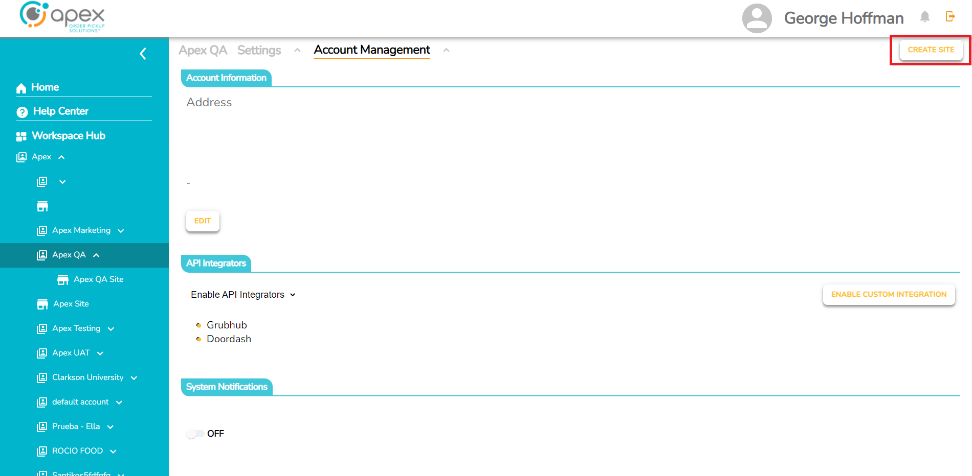
Click the Account Management dropdown and select Account Management again from the dropdown to proceed to this menu screen.
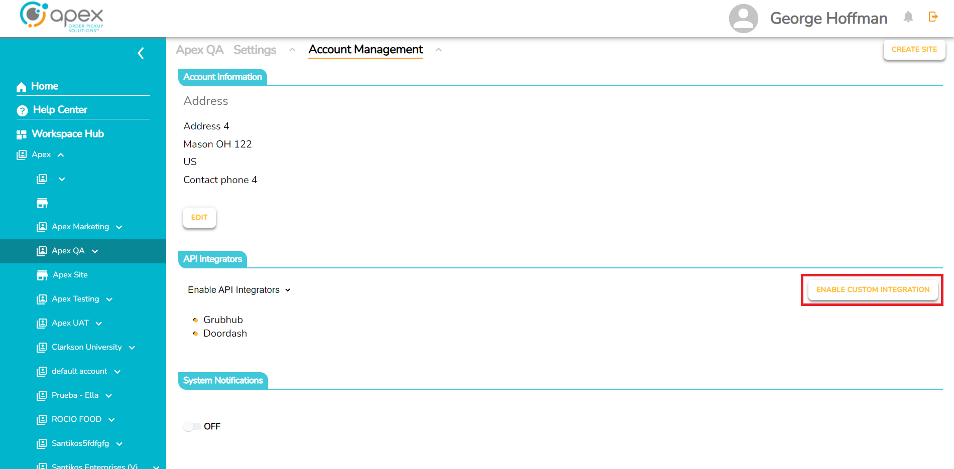
Finally, click the ENABLE CUSTOM INTEGRATION button.
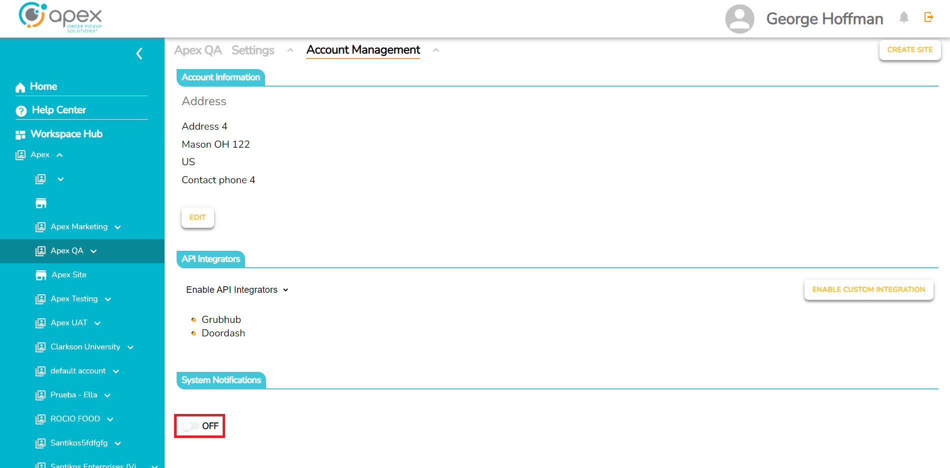
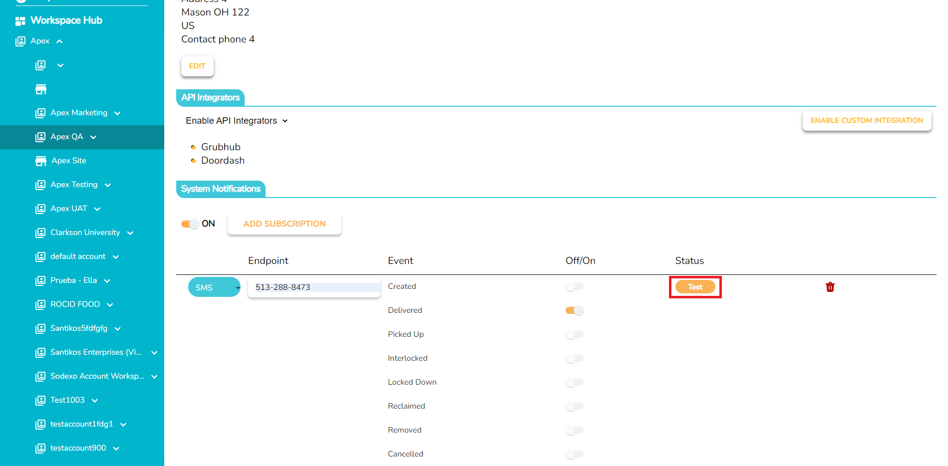
Enable System Notifications
Click the workspace dropdown menu.
Click the down arrow next to the company (Apex in this example).
Click the desired Account (Apex QA in this example).
Click the Account Management dropdown and select Account Management again from the dropdown to proceed to this menu screen.
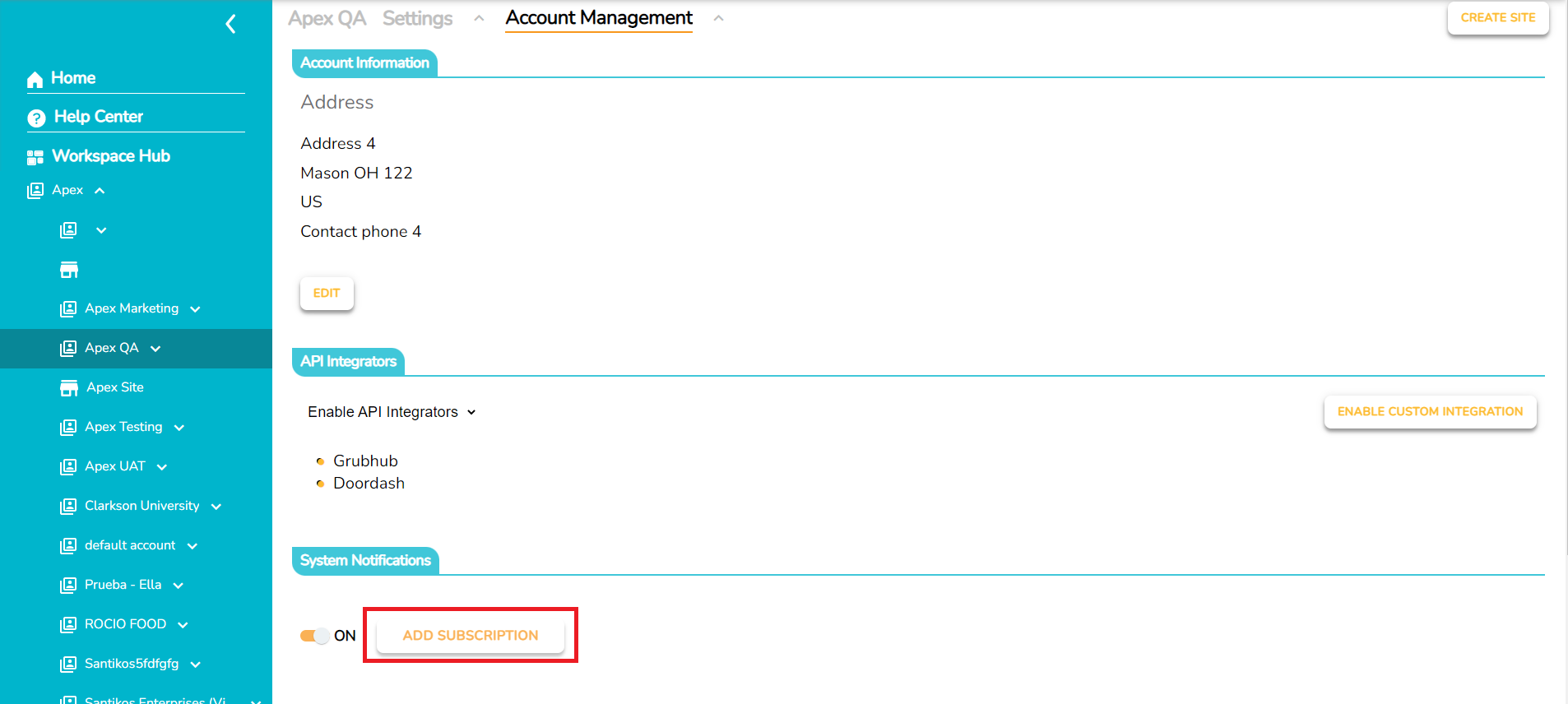
Toggle the System Notifications slider to ON.
Click the ADD SUBSCRIPTION button.
Configure the desired endpoint and event selections.
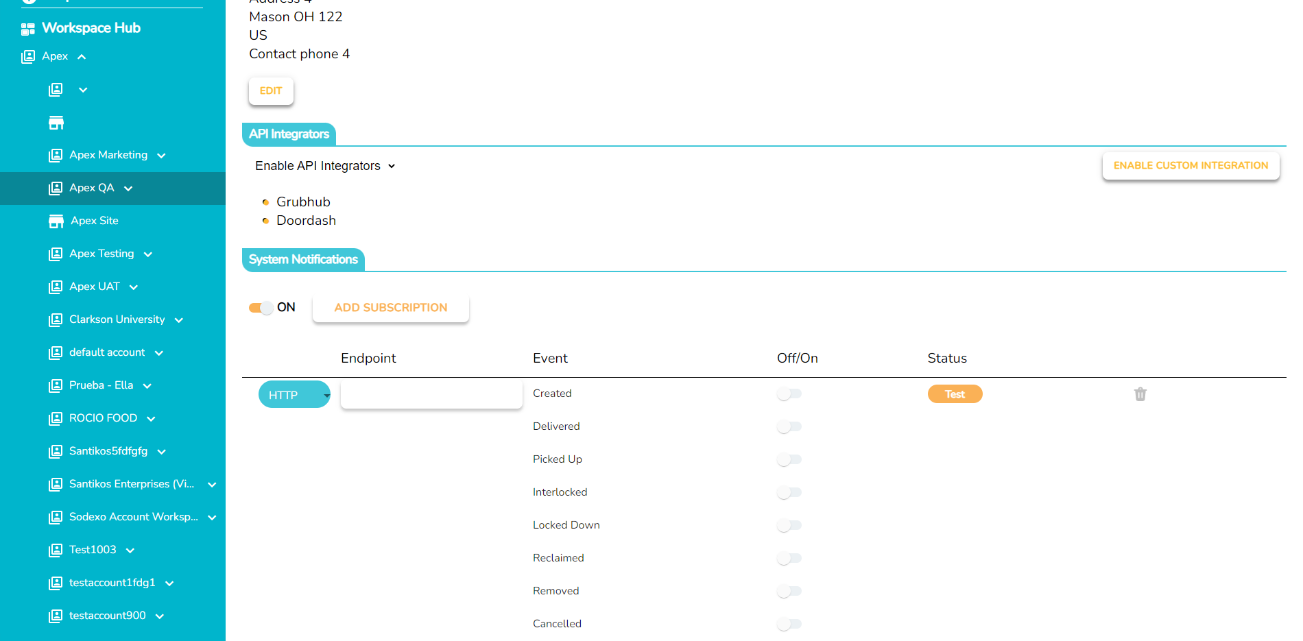
A message will indicate success at the bottom of the screen when the event type is toggled ON. If the toggle is turned back to the OFF position, a message will display the update on that specific event.
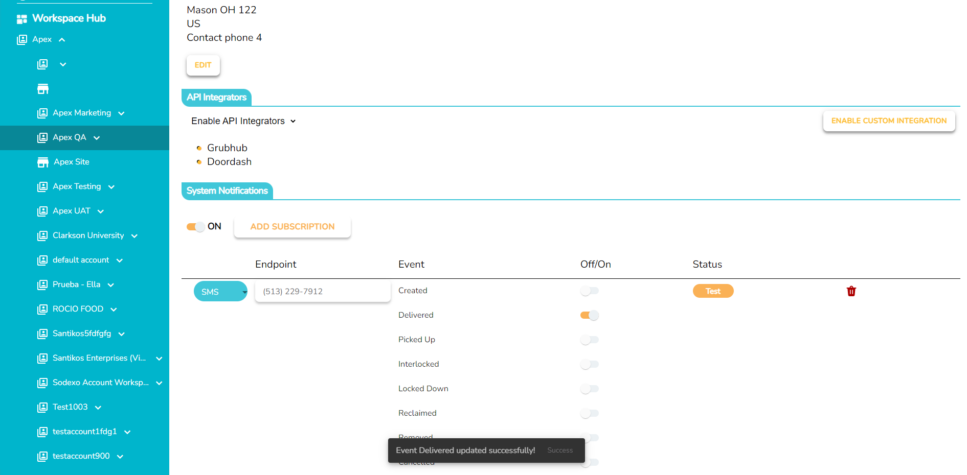
Click the Test button to ensure the event subscription is working.
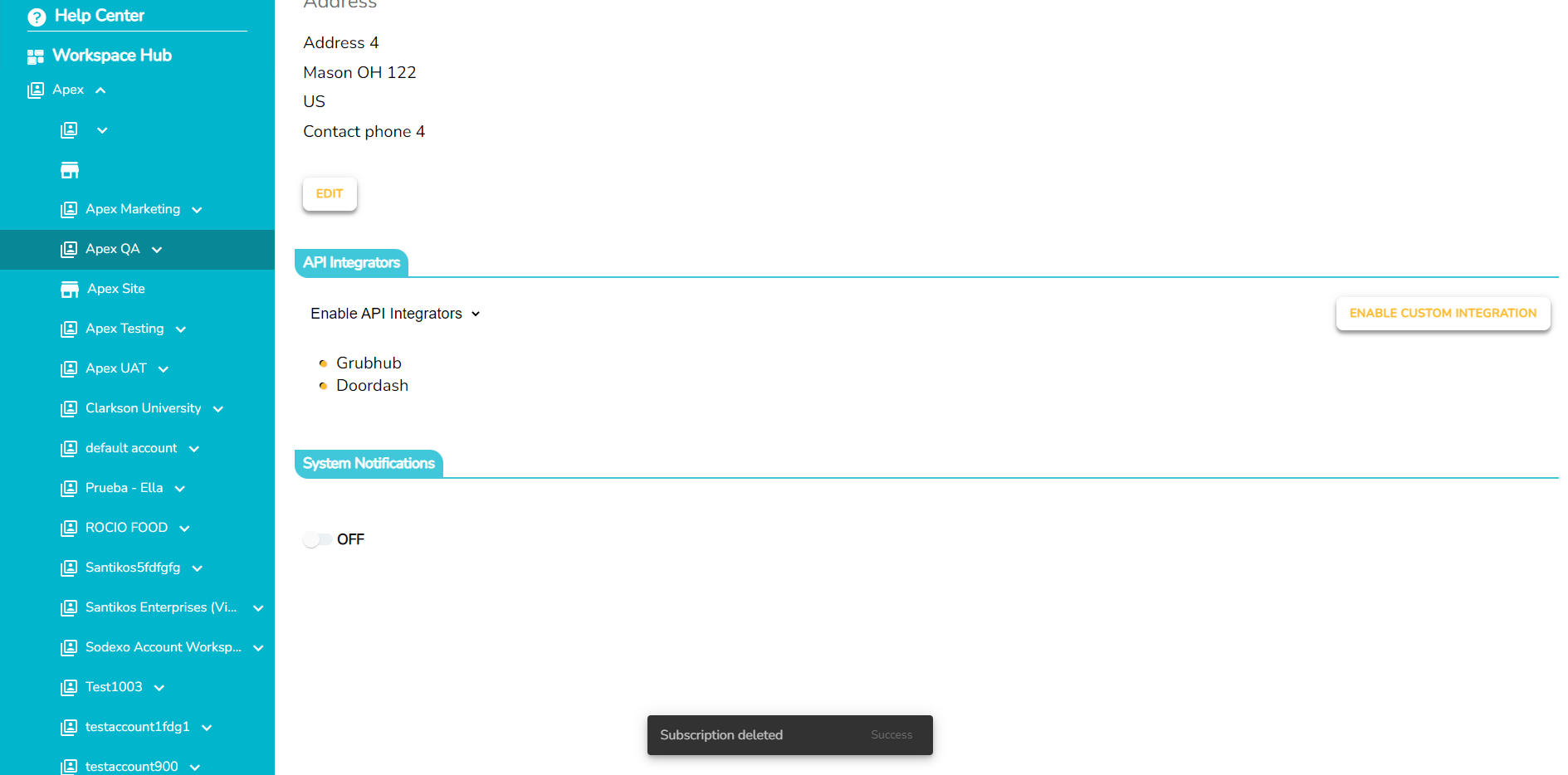
To delete the event subscription, click the red trashcan icon.
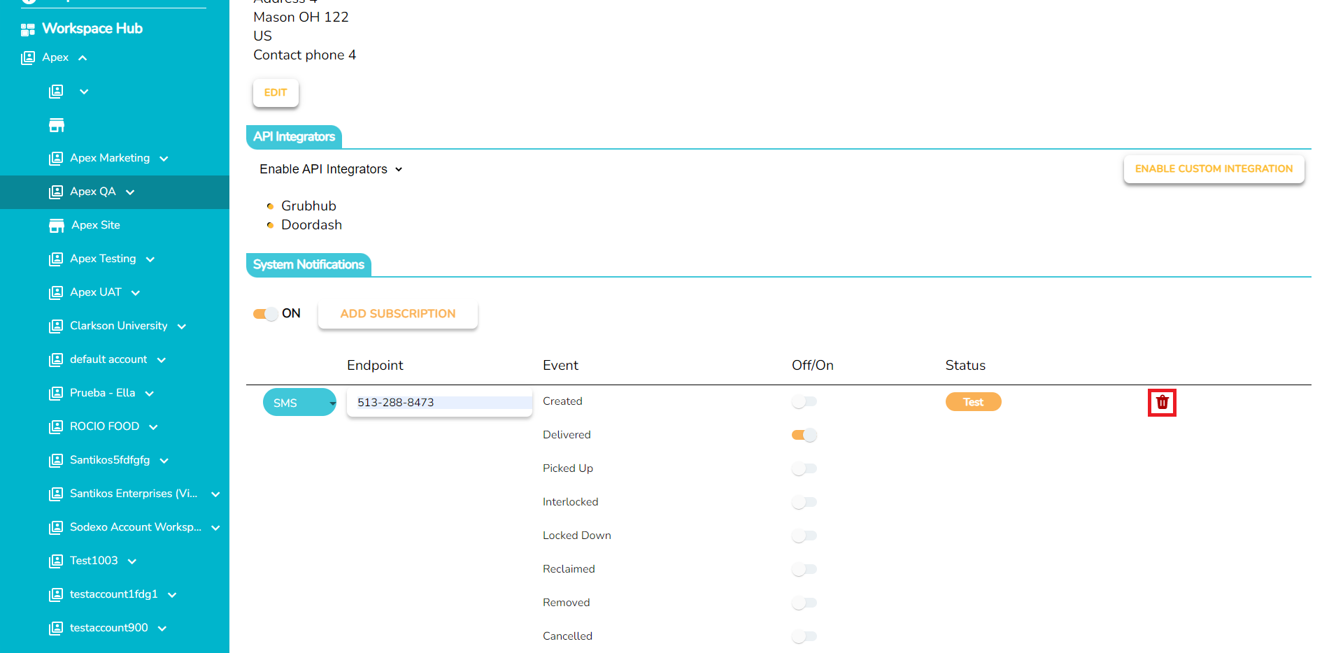
Click the YES button to delete the endpoint.
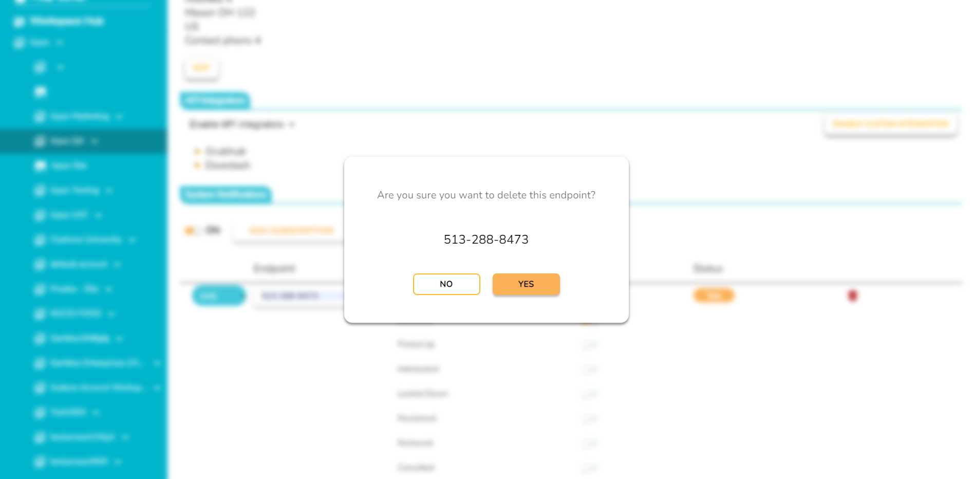
A message will display success for Subscription Deleted.
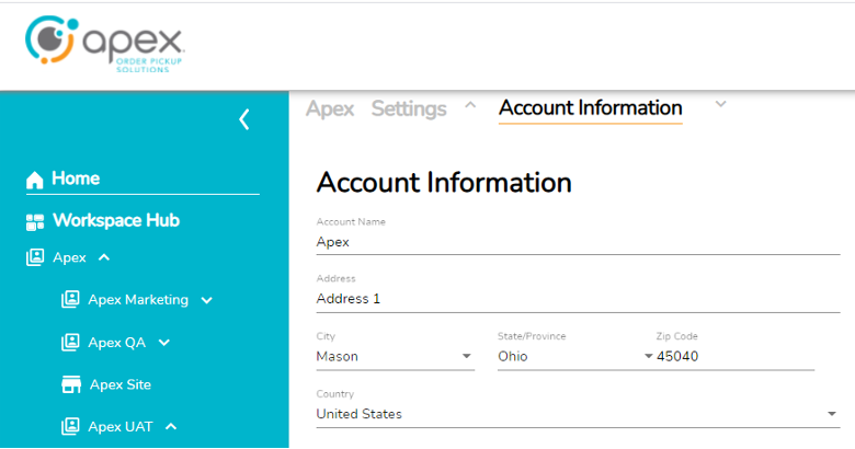
Account and User Management
Account Information is a very basic layer that lives under the Account Management section of the page header and allows for Account information to be Created and Managed/Edited.
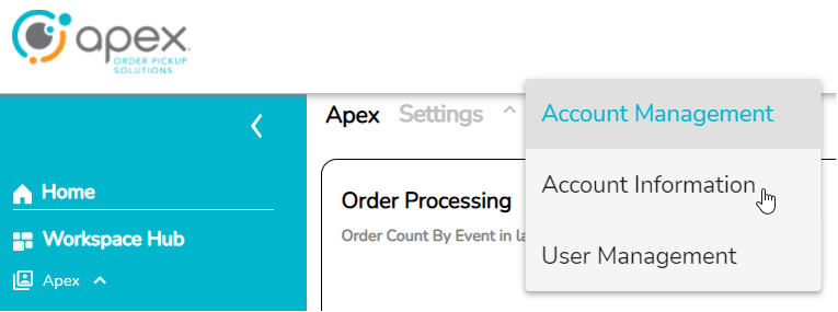
User and Permission Management
User Management also lives under the Account Management section of the page header and allows for the creation, management and deletion of AIQ Portal Users.
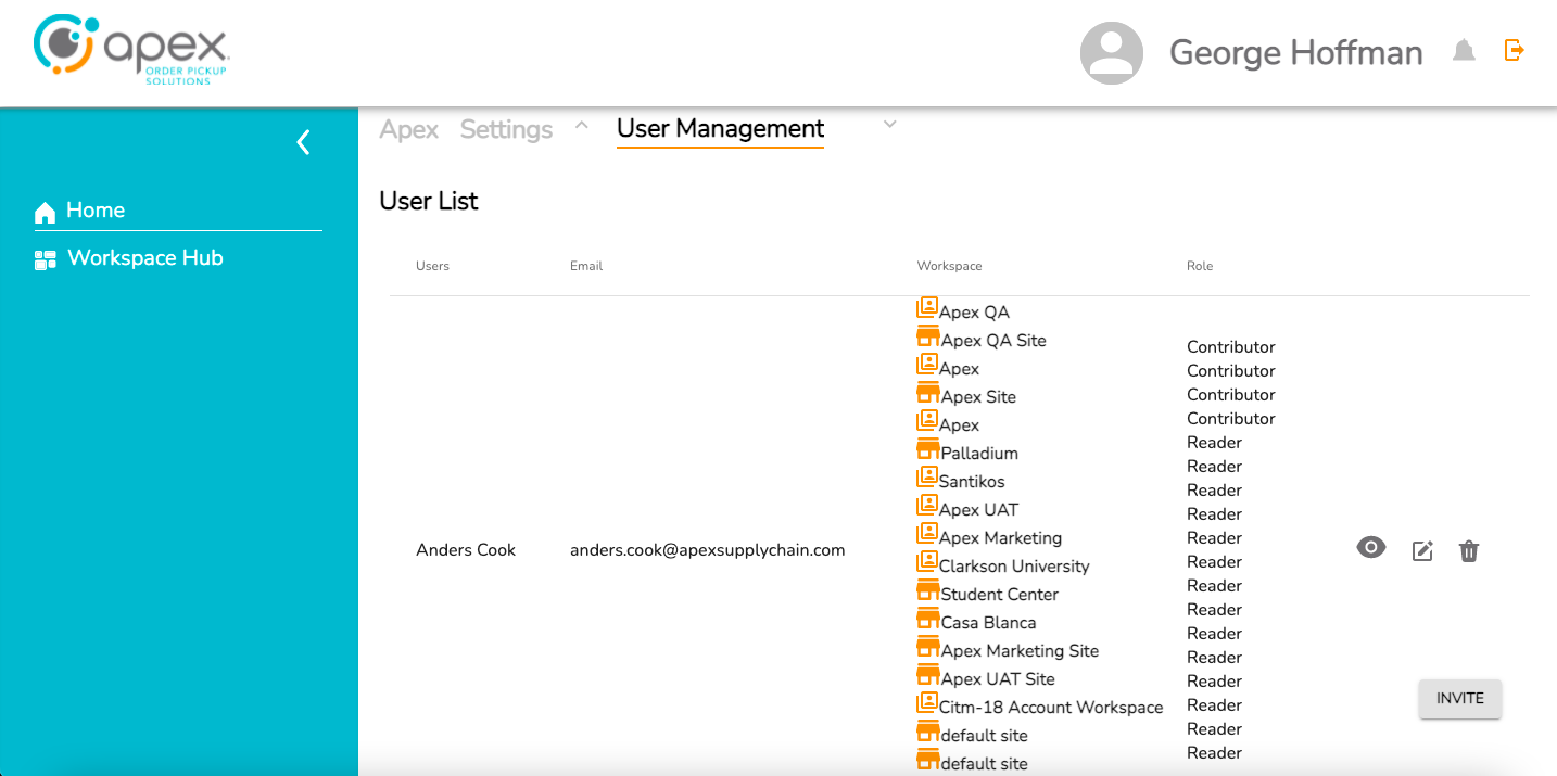
The full user list currently displays the following information:
Users – User name as supplied/entered.
Email – Email address supplied/entered.
Workspace – The various workspaces the user can access in the AIQ Portal.
Role – The permission level for each workspace the user can access.
Eye/Edit/Trash Icons – These are currently not yet functional but they should allow a user to view, edit and delete another user.
Invite - Adding a User: The invite button in the bottom right of the page is where a user would go to create a new AIQ Portal User.
Manage API Integrators
Starting at the company level on the left side pane, navigate to the API Integrators tab located top center.
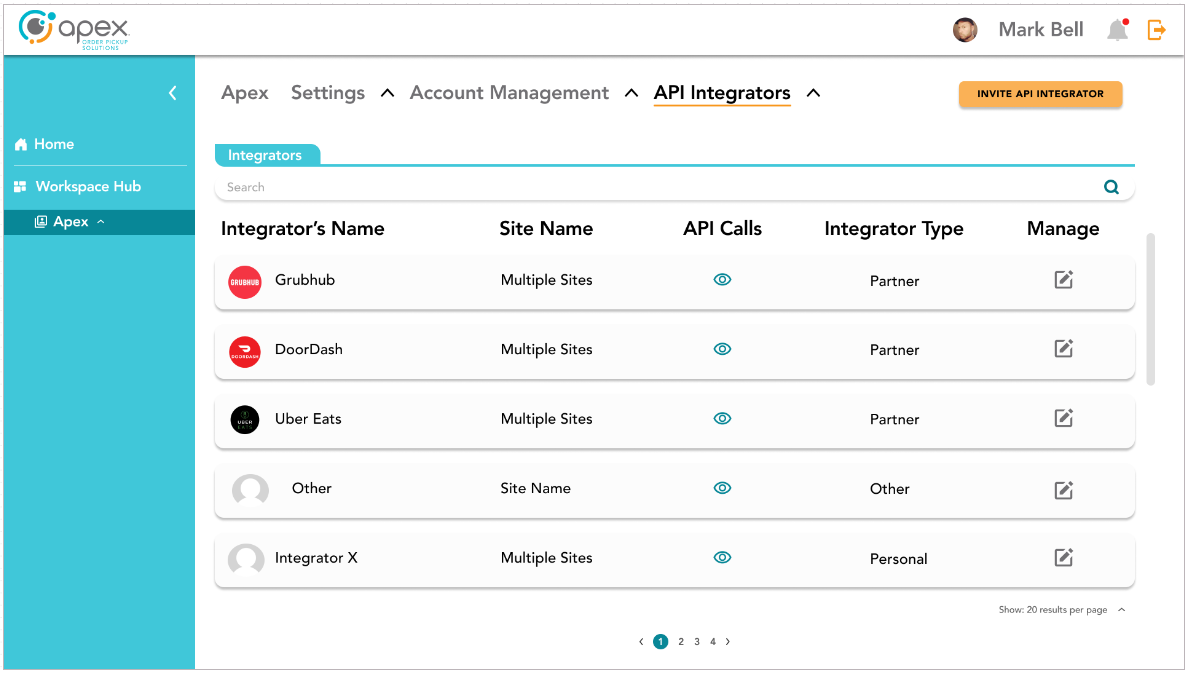
Find the desired integrator and select the pencil box icon to open the management screen. The number of results per page can be edited to show 20, 50 or 100 results.
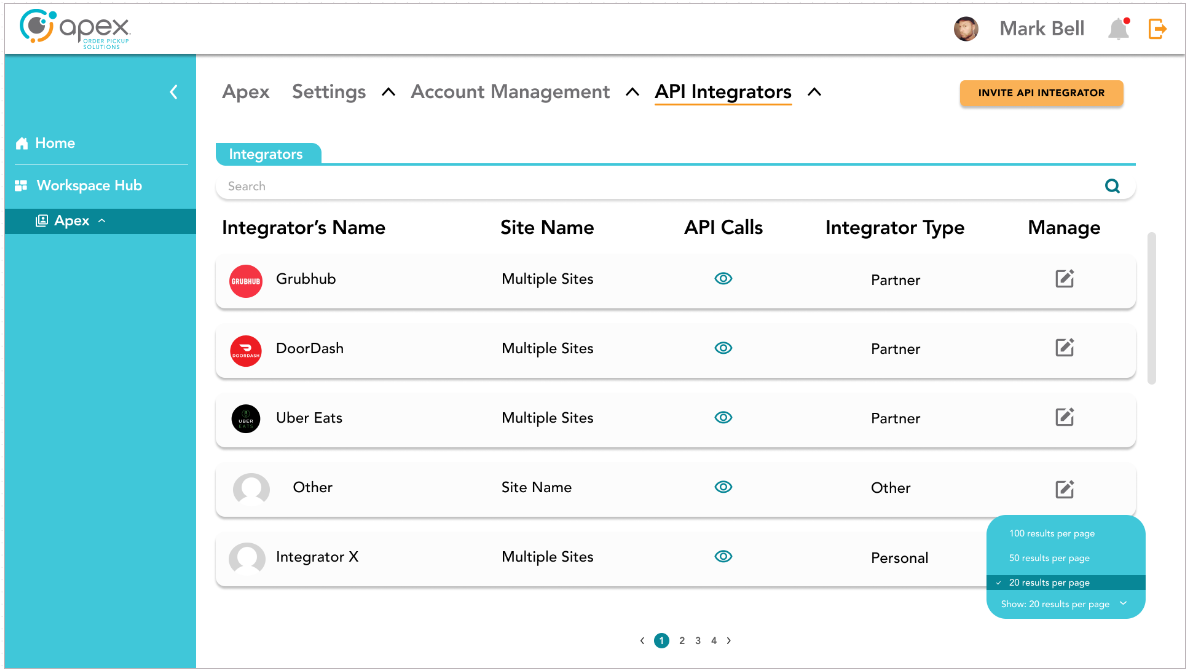
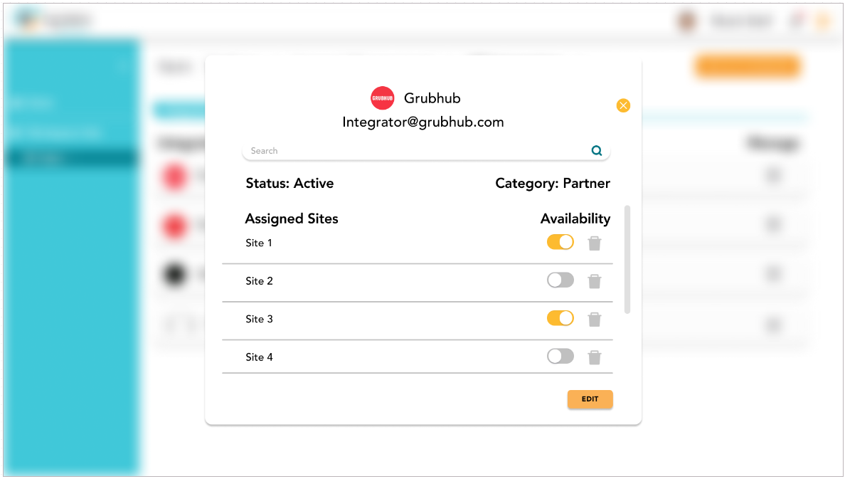
On the integrator management screen, users are shown a searchable list of sites. There is a toggle on/off switch for each site integration with the ability to delete the site integration.
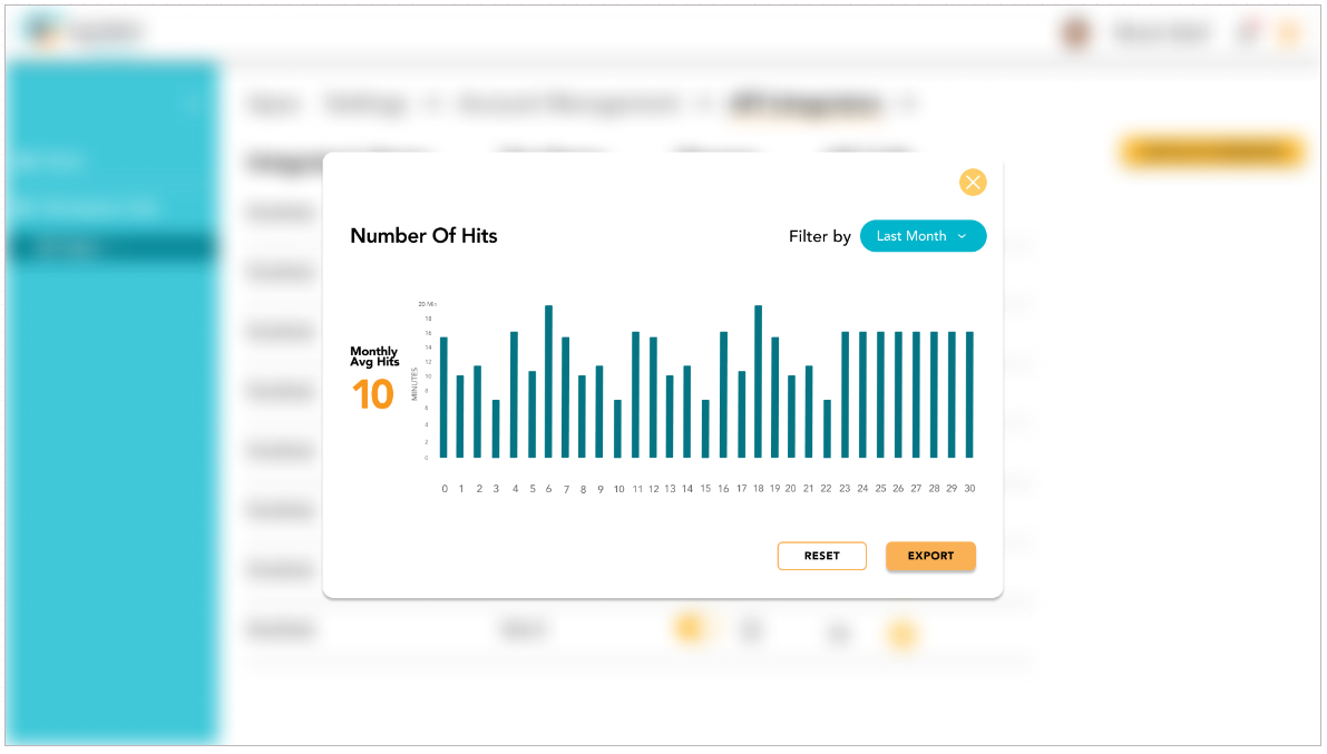
Finally, users can view the Number of API Calls by selection the eye icon on the API Integrator screen. This chart can be filtered by length of time and can be exported as a .xls file.
Settings and Configurations
The settings dropdown contains the General page, Notifications and Participants.
Notice
Currently, some settings are not able to be changed. Future versions of the product will add functionality.
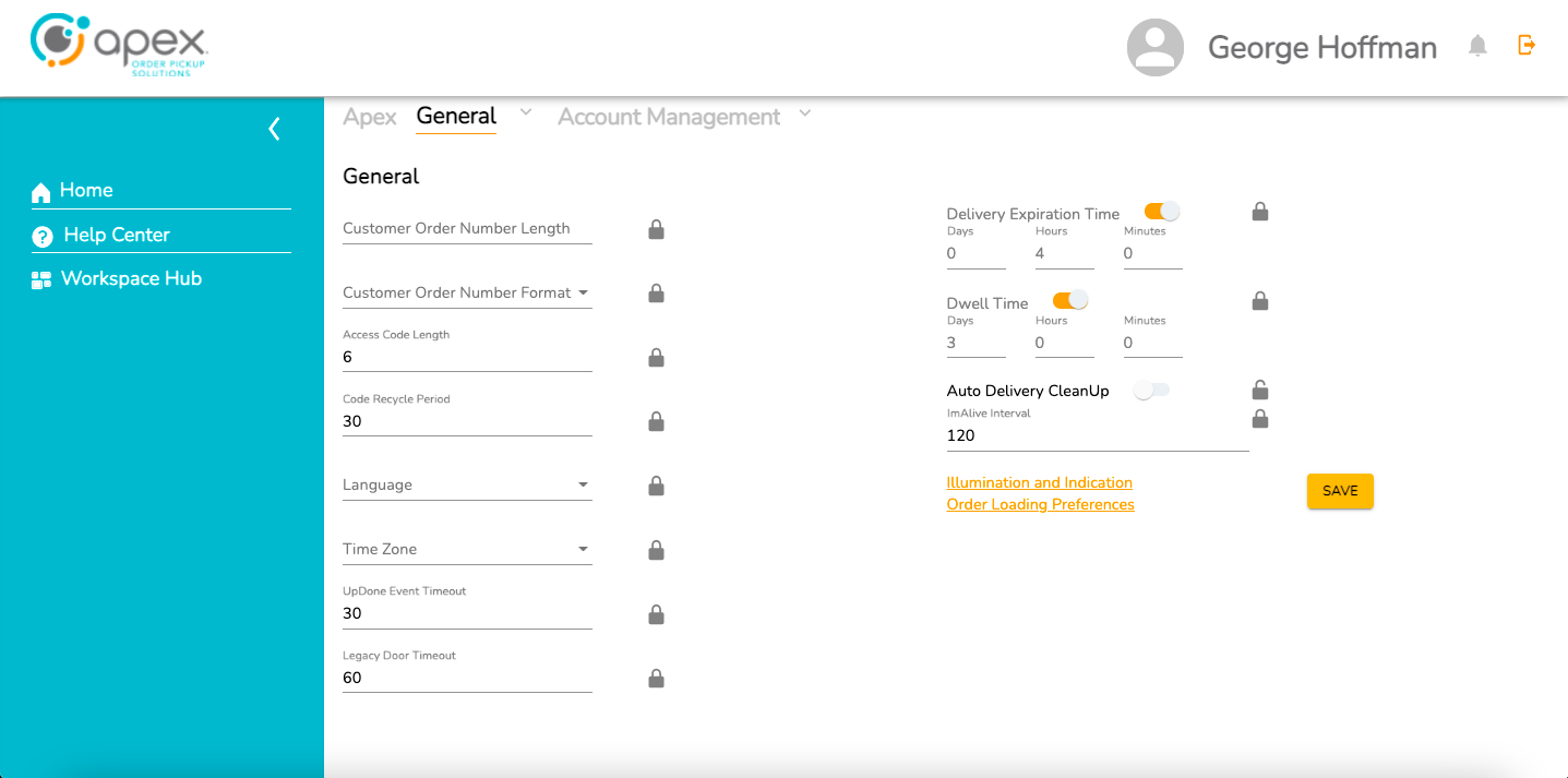
The General page is where users can find all of the available customization options. Here users can tweak the following parameters:
Customer Order Number Length
Customer Order Number Format (Numeric or Alpha)
Access Code Length (Min & Max value)
Code Recycle Period
Language (English, German, French and Spanish)
Time Zone
UpDone Event Timeout
Legacy Door Timeout (toggle on/off)
Delivery Expiration Time (toggle on/off)
Dwell Time (toggle on/off)
ImAlive Interval
There are also links to pages for Illumination and Indication Preferences and Order Loading Preferences.
The first page of Illumination and Indication Settings allows the user to set custom hex color values for the following indicators:
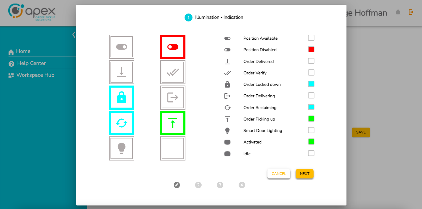
Position Available
Position Disabled
Order Delivered
Order Verify
Order Locked Down
Order Delivering
Order Reclaiming
Order Picking Up
Smart Door Lighting
Activated
Idle
The 2nd page of Illumination and Indication settings allows the user to set custom hex color values and toggle on/off the blink and state of the following indicators:
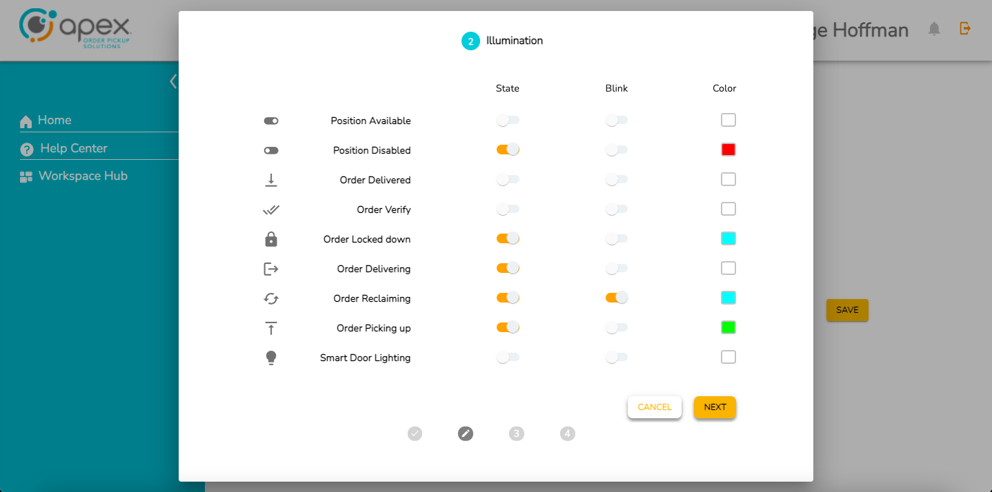
Position Available
Position Disabled
Order Delivered
Order Verify
Order Locked Down
Order Delivering
Order Reclaiming
Order Picking Up
Smart Door Lighting
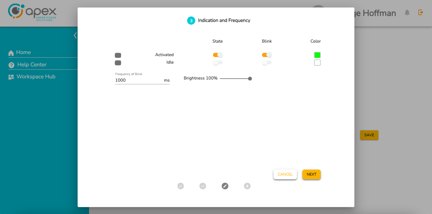
The 3rd page of Illumination and Indication Settings allows the user to set indication and frequency settings. The user can set custom hex color values, toggle on/off the blink and state of Activated and Idle indicators. The user can also set the frequency of the blink (in milliseconds) and the brightness (0-100%).
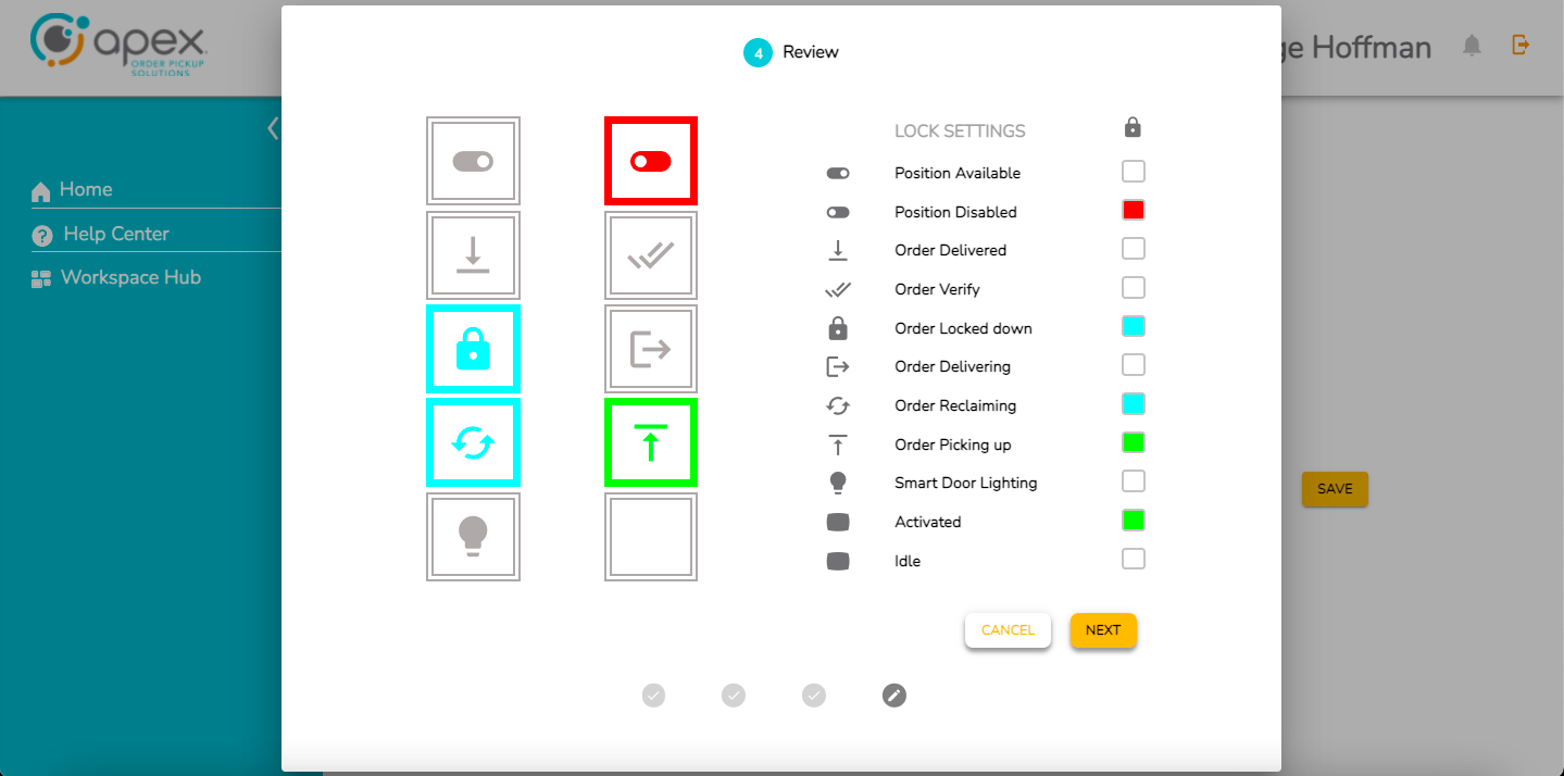
The 4th and final page of Illumination and Indication Settings lets the user review their selections and lock settings. It shows a summary of the customizations a user has set before applying the changes. The user can reject the changes by clicking cancel or accept the changes by clicking done.
The Select Loading Preference page allows the user to set the order in which compartments are loaded.
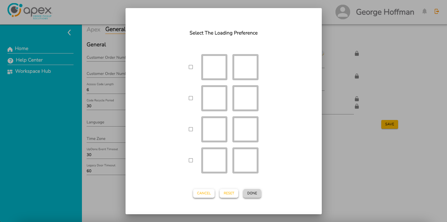
Users click the compartment check boxes in the order they would like loading to occur.
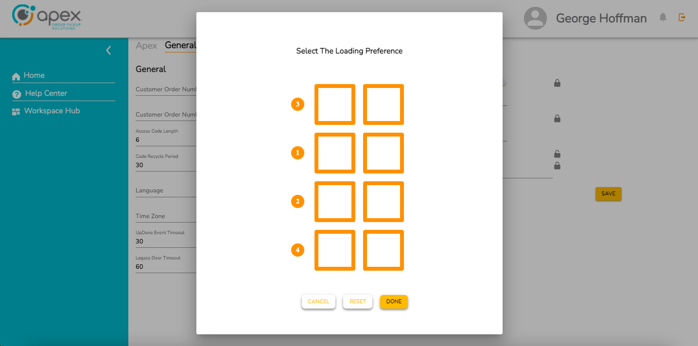
The user set loading order preferences can be reset to default by clicking reset, rejected by clicking cancel or accepted by clicking done.
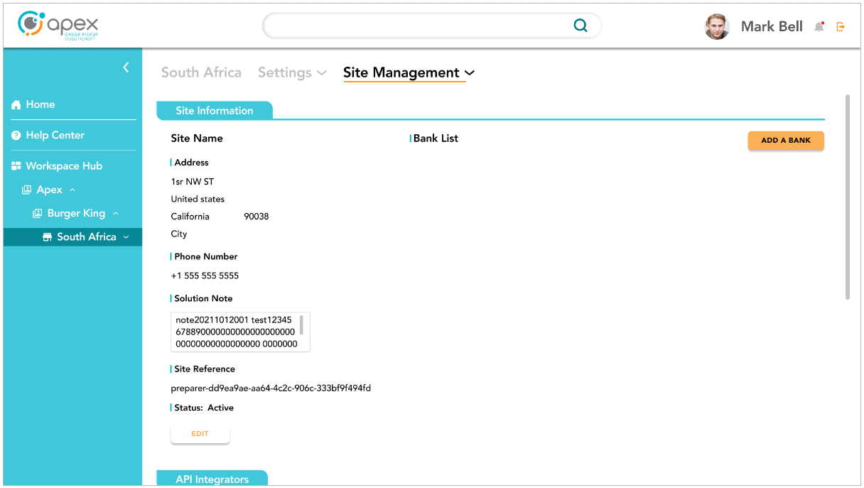
Site Management
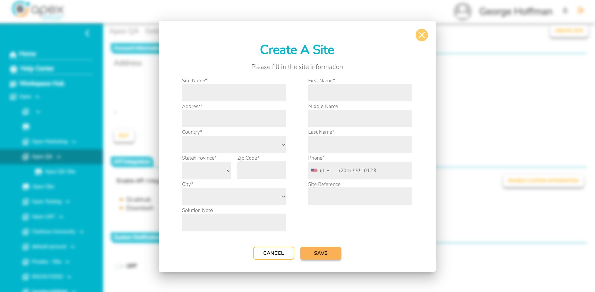
Create a Site
Click the Workspace dropdown menu.
Click the down arrow next the the company.
Click the desired account.
Click the Account Management dropdown and select Account Management again from the dropdown to proceed to this menu screen.
Click the CREATE SITE button at the top right of the screen.
Fill in the required fields, then click the SAVE button.
Activation
Select the desired site to activate a device. Click the Add a Bank button.
Use the activation code supplied by the Associate UI and enter it into the field. Click the activate button.
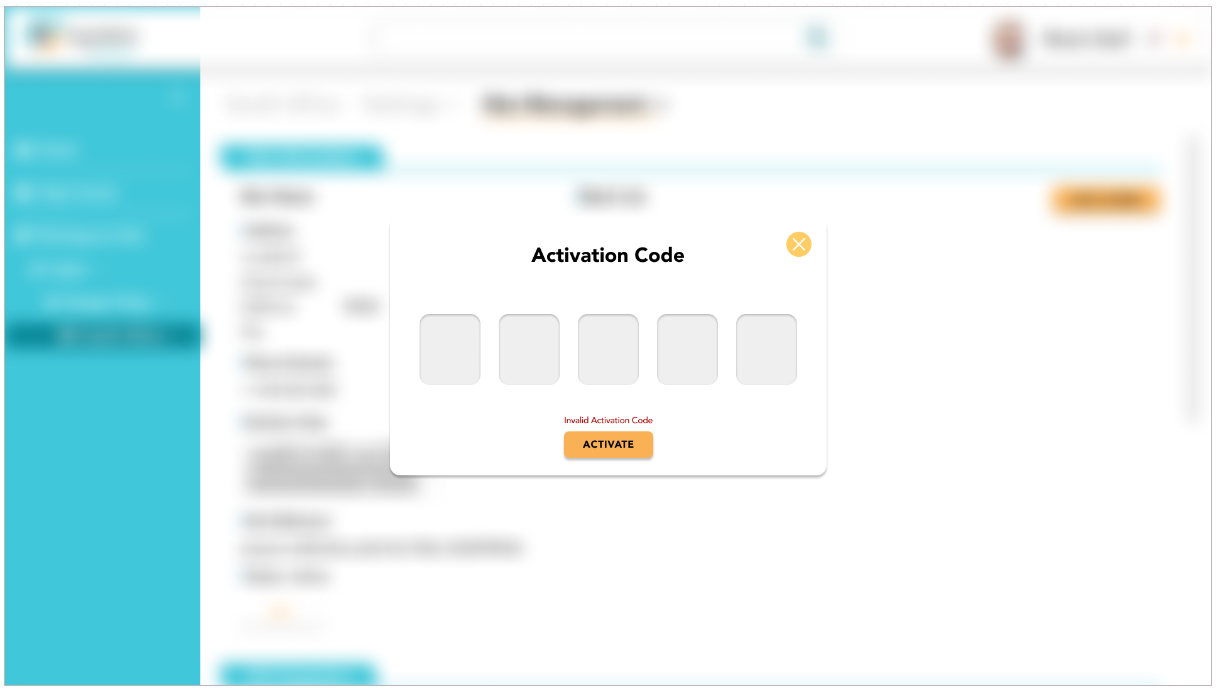
A green dot next to the Bank will indicate that the device has been successfully activated. Check the serial number and locker number(s) to ensure device information is accurate.

Test each locker to ensure proper operation by clicking the test button next to each locker. Order the lockers as desired and click the save locker order button.
Allocation and Activation Guide
Introduction
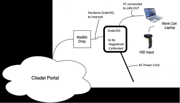
Introduction: This document describes how to register or update the registration, calibrate and certify the final assembly of an OrderHQ Flow-Thru 107.
Purpose: Required steps to register a locker on the Portal.
Prerequisites:
Gather the kit and cables, connect as shown below:
Create an Apex Order IQ online portal account here
Request to be granted a device registration role
Login to the Portal and register a device
Access the account on the Apex Order IQ Portal using a Chrome, Safari, Firefox or Edge web browser.

Upon login, the user will be automatically directed to the Locker Registration dashboard.
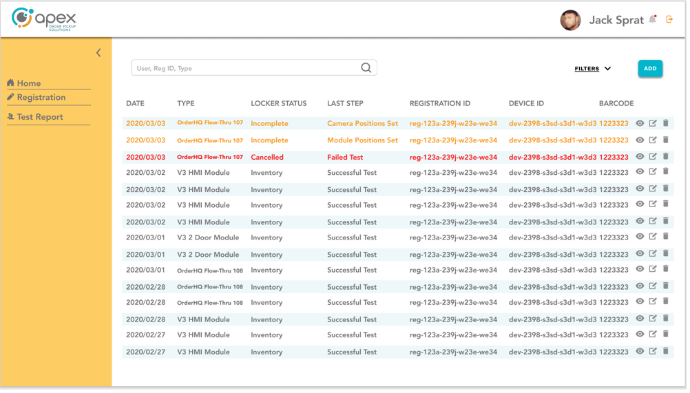
To register a new locker, click the "ADD" button.
Select Locker Type from the pull-down menu.
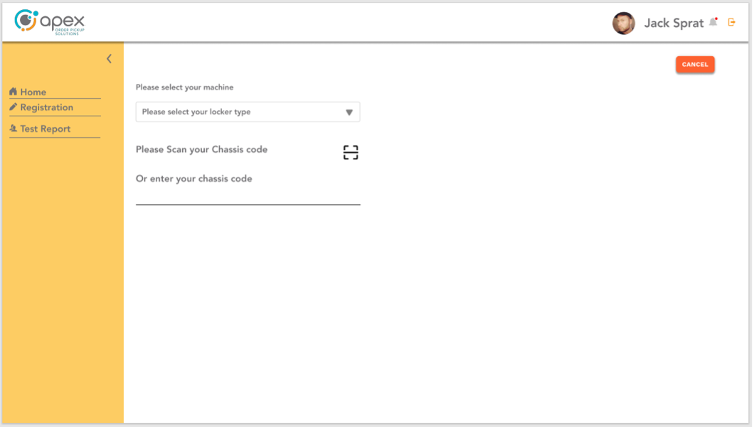
Caution
The Locker Type must match the model of the locker you are testing.
Scan the serial label barcode on the back of the locker for the Chassis Code.
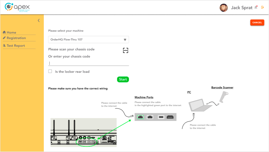
Click the "Start" button to begin the testing.
Notice
If the locker is a rear load model, there will be additional steps for IEI certification.
Configure the NUC
Input the NUC Pairing Code into the HMI Screen on the customer facing side of the locker.
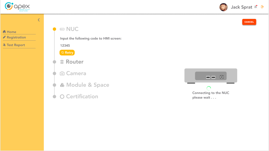
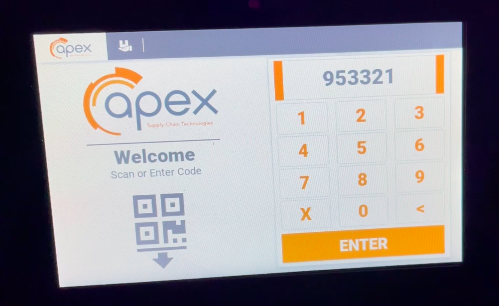
The NUC serial number will populate.
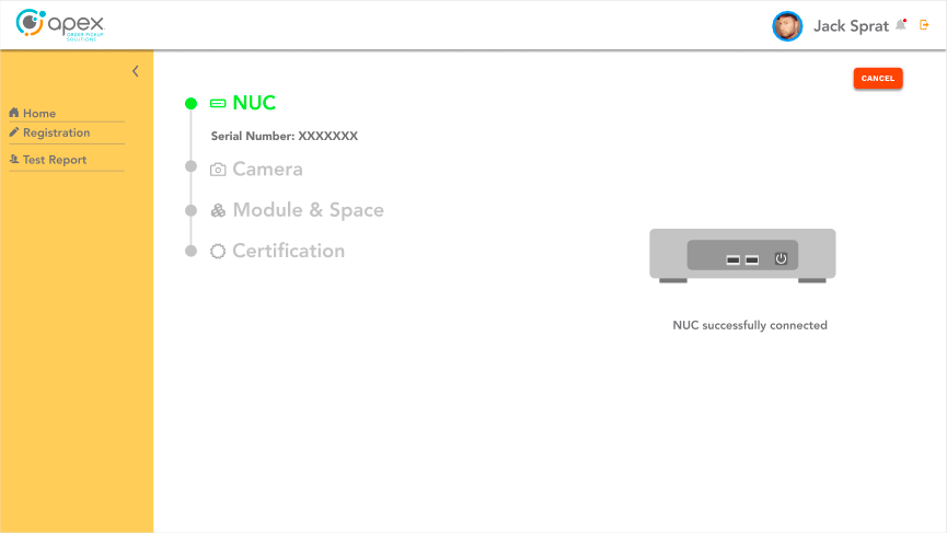
Configure the Router
Scan the printed picture of the code supplied with the power module.
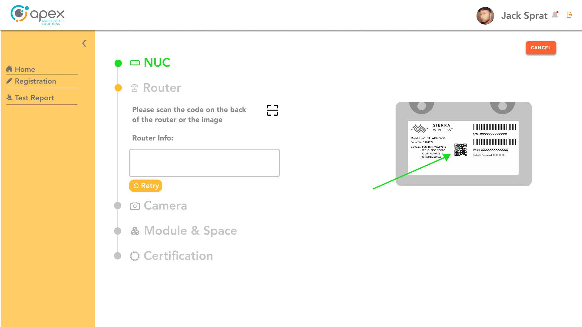
The serial number and default password will auto populate their respective text fields.
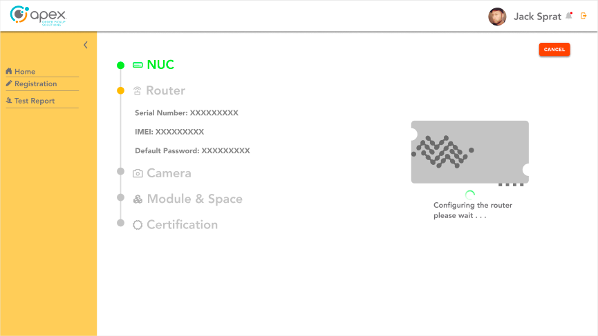
Configure the Cameras
Verify that all doors are open and then click "Pass".
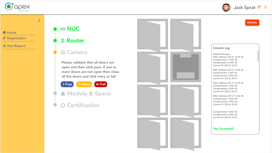
Doors should be open a minimum of six inches.
In the event of a fault, follow the onscreen instructions to retry or fail.
Place each numbered card in its respective compartment with the QR code facing upwards.
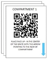
Click "Pass".
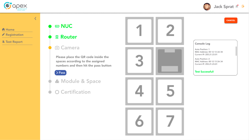
Verify the number of the images from the cameras matching the number of locker compartments.
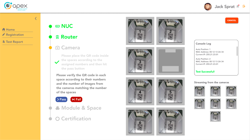
Click "Pass".
Verify that all doors are open and then click "Pass".
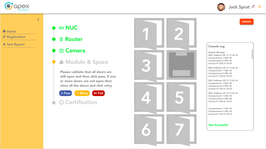
Close door #1.
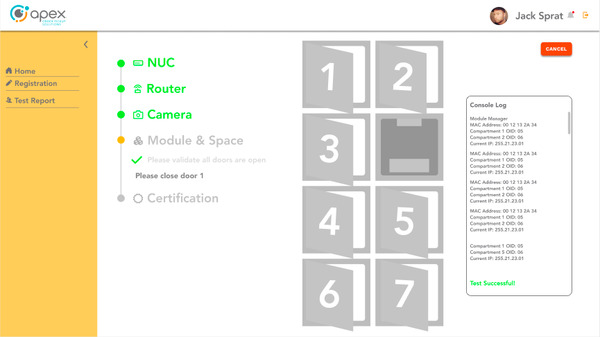
Click "Pass".
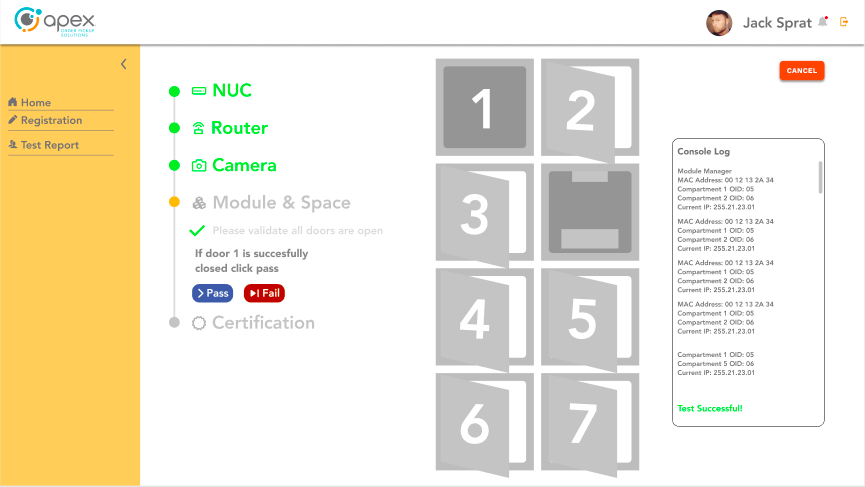
Close door #2.
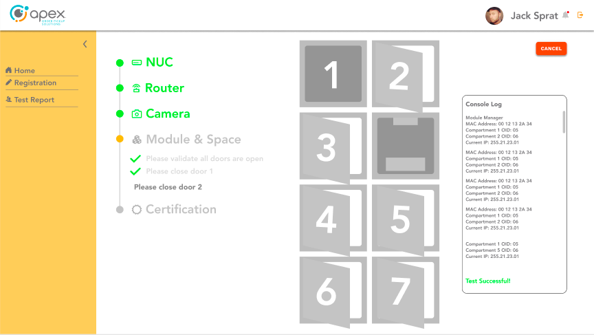
Click "Pass" and repeat for each of the remaining doors.
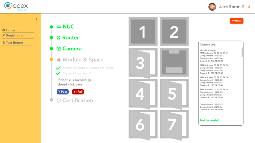
All doors will open automatically.
Remove each QR code card from each compartment one at a time as you progress through each individual door.
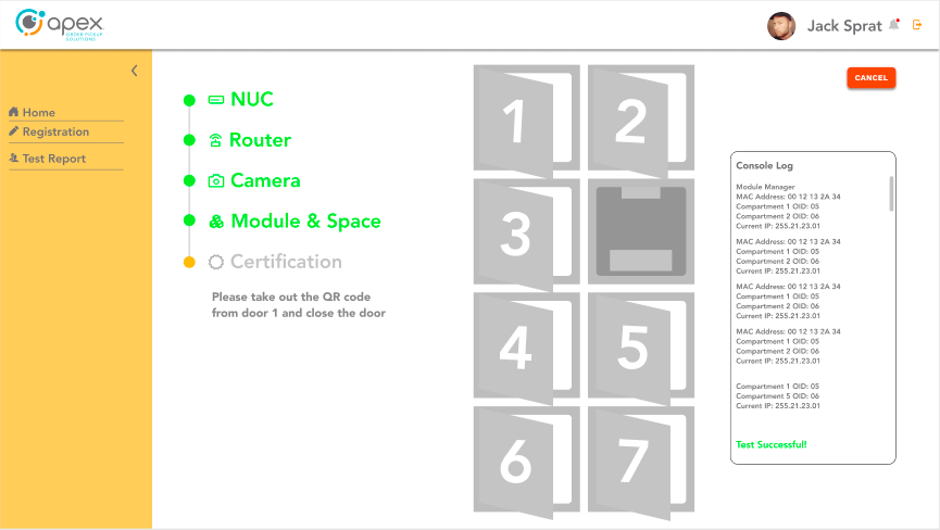
Close door #1.
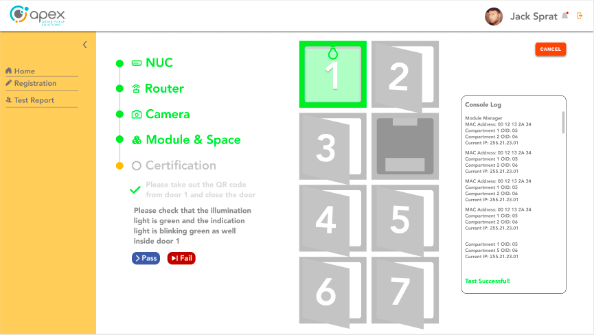
Check that the illumination light is green and and the indication light is blinking green inside of door #1. Press "Pass".
Close door #2.
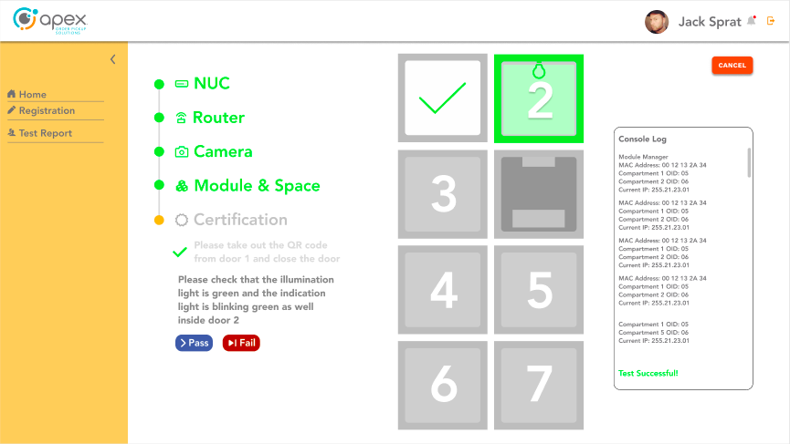
Check that the illumination light is green and and the indication light is blinking green inside of door #2. Click "Pass".
Repeat this process for all remaining doors that require certification.
Complete the certification process
Confirm that you see "1" on the HMI screen, then click "Pass".
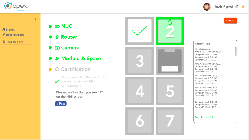
Confirm that you see "TEXT" on the panel PC, then click "Pass".
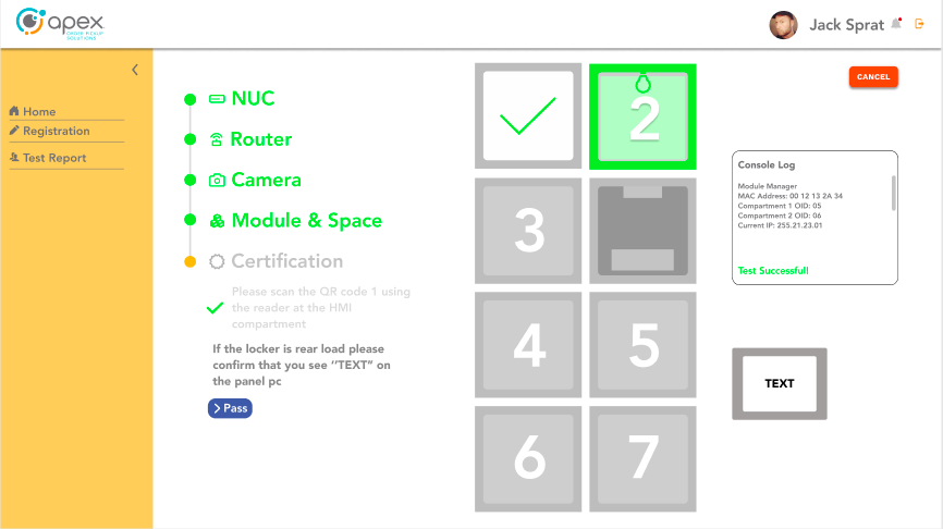
A certification report will automatically be generated.
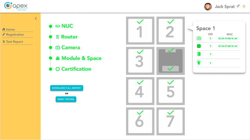
The user can download the certification report by clicking "Download Full Report".
Device Management Utility
Introduction
The Device Management Utility is designed to enable users to manually step through the testing, configuration and calibration processes for Apex OrderHQ Flow-Thru devices.
Device Management Utility
Plug in only the power supply on the manufacturing PC.
Warning
Do not connect any ethernet cables at this stage! If done by mistake, disconnect ethernet cables, power off the PC and start over.
Connect the manufacturing PC to the LAN OUT port of the device using a Cat5e or Cat6 cable.
Connect the AC Power Cord to the Apex OrderHQ device and Power ON the device.
Once booted up, open a web browser and navigate to the following IP address: 192.168.13.100:1800/ui
Router Configuration
Scan the QR code that is on the bottom of the router. An audible beep will sound.
Important
Cover the 3 barcodes so they are not read.
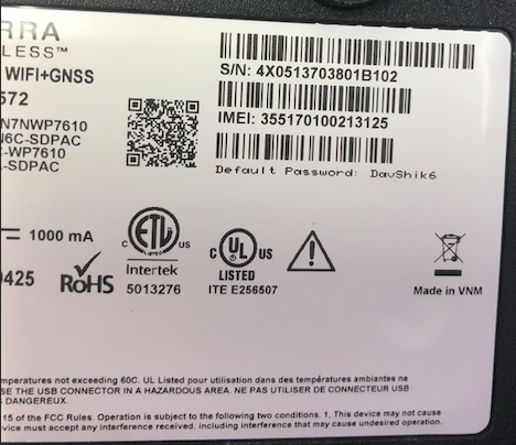
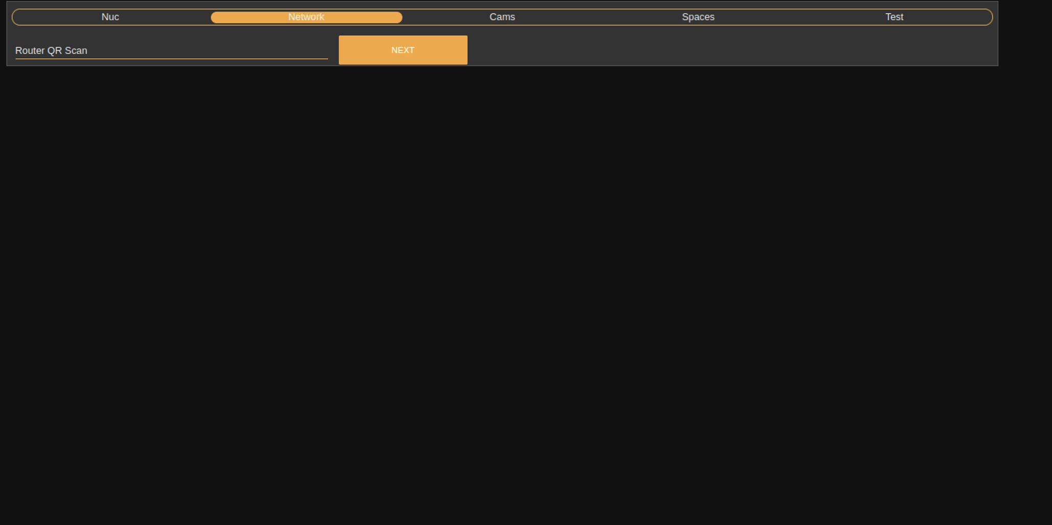
A script will run and the initial router template will be set.
Notice
This process will take several minutes.
Once the script has finished running, plug in the ethernet cable to the INTERNET IN port.
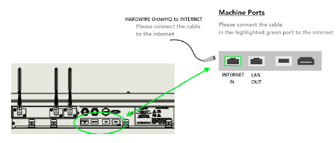
Power OFF the device, wait at least 15 seconds and then power ON the device.
HMI Scanner Configuration
Confirm that both the front and rear HMIs are powered on and the Apex/Merco logos appear on both screens.
Scan the QR code using the scanner on the front of the device above the screen.
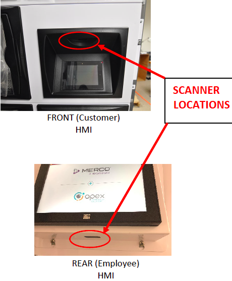
Verify the scanner is operating. This is indicated by two audible beeps.
Scan the QR code using the scanner on the rear of the device below the screen.
Verify the scanner is operating. This is indicated by two audible beeps.
Using the manufacturing PC, open browser and navigate to 192.168.100.1.1800/ui Proceed to NUC configuration.
If step 6 fails, follow the below procedure:
Disconnect the ethernet cable.
Press and hold the reset button on the router.
Wait 30 seconds.
Power cycle the entire device after resetting the router.
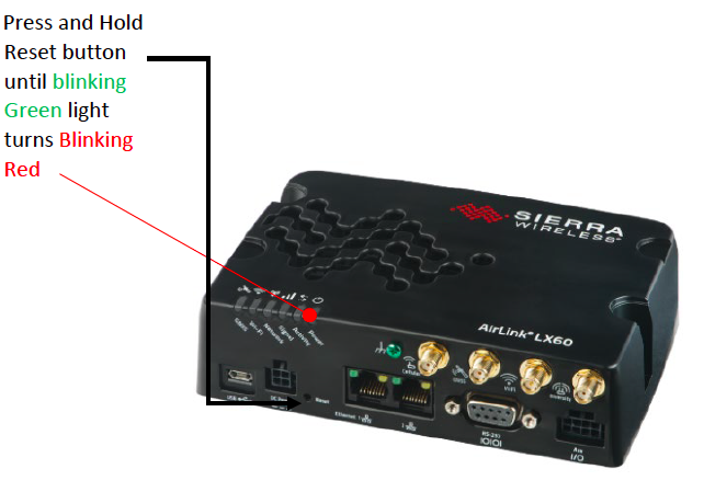
NUC Configuration
Scan or enter the barcode on the NUC into the NUC Serial Number field and click Next.
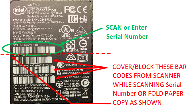
Scan the chassis QR code on the serial number label at the rear of the unit to populate the chassis serial number field.
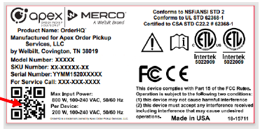
Click NEXT.
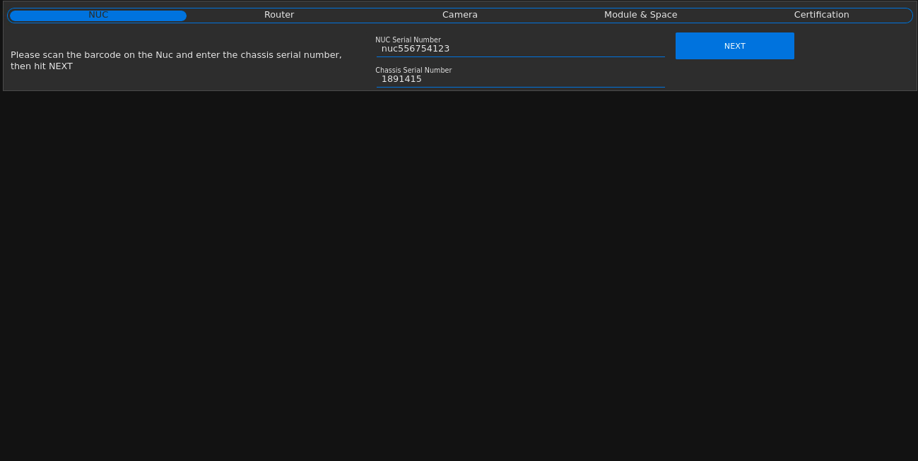
Note
The field for "Add on Chassis Serial" is reserved for adding additional capacity, otherwise disregard this field.
Proceed to the LED test.
LED Test
In order to ensure that equipment is fully functional, users will run a series of LED tests to verify accurate illumination of red, green, blue and white light across all device compartments.
Warning
If any lights fail to illuminate as intended, contact your supervisor. Do not attempt to complete the end of line setup if any lights appear to be malfunctioning.
Click Execute LED Test to begin testing device LEDs.
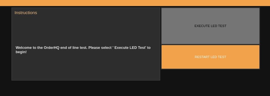
The first test will illuminate red light in each compartment. Visually inspect and verify that each compartment illuminates red. Click ALL LIGHTS ARE RED to proceed to the blue light test.
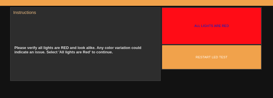
The next test will illuminate blue light in each compartment. Visually inspect and verify that each compartment illuminates blue. Click ALL LIGHTS ARE BLUE to proceed to the green light test.
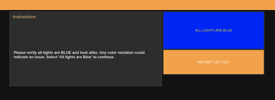
The next test will illuminate green light in each compartment. Visually inspect and verify that each compartment illuminates green. Click ALL LIGHTS ARE GREEN to proceed to the white light test.
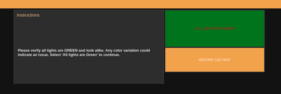
The final test will illuminate white light in each compartment. Visually inspect and verify that each compartment illuminates white. Click ALL LIGHTS ARE WHITE to proceed.
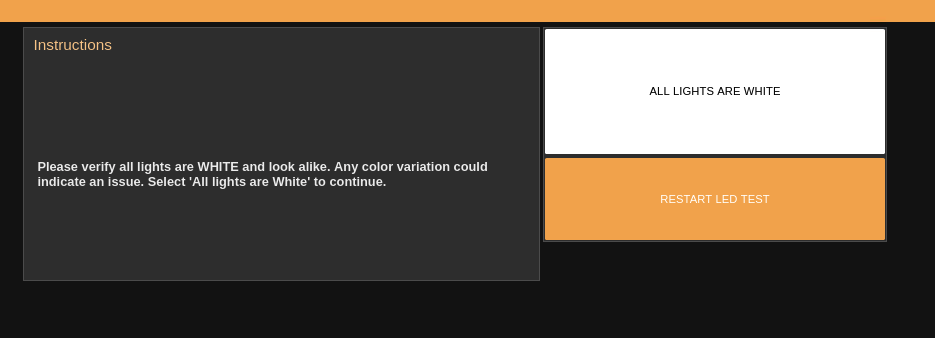
Click FINISH LED TEST to complete the LED Test process.
Proceed to the camera configuration.
Camera Configuration
Verify that all doors are open and then click PASS. If one or more doors are not open, close all of the doors and press RETRY.
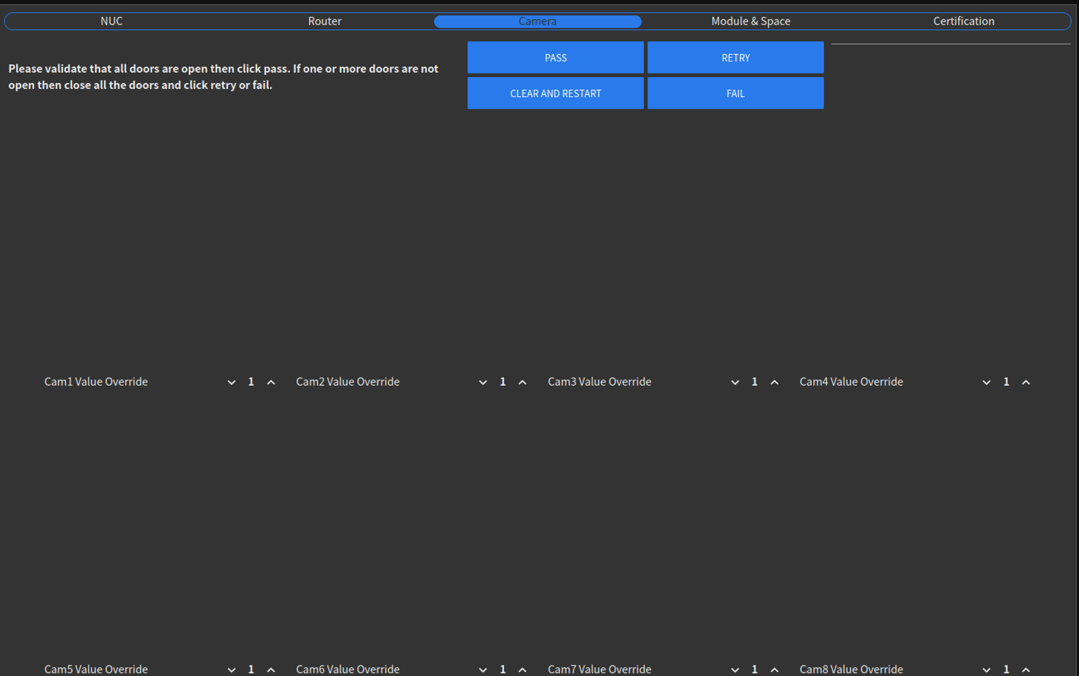
Important
Doors should be open a minimum of 6 inches.
Place the numbered QR code cards into their assigned spaces, then click Ready.
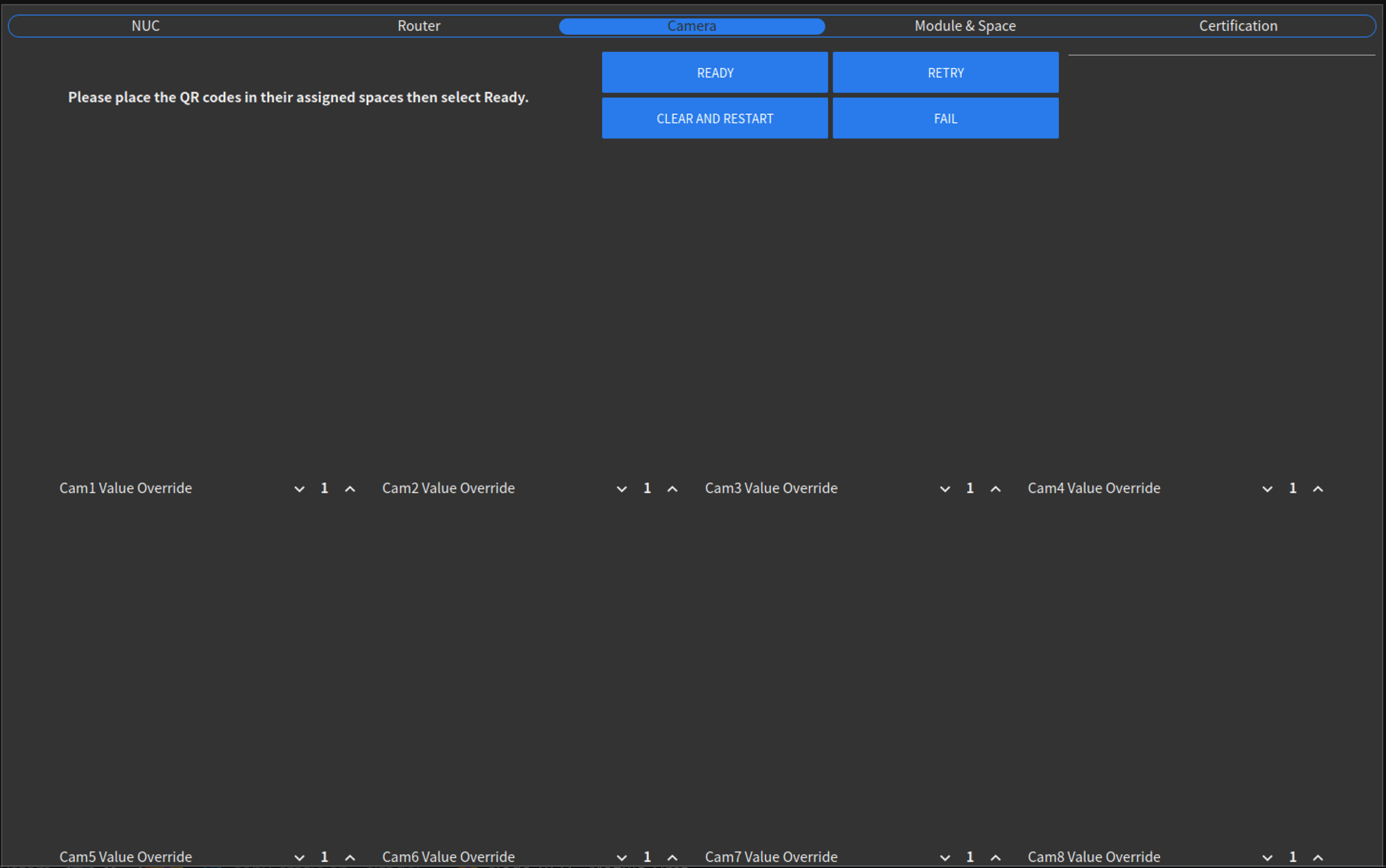
Note
For best results, place the cards with their numbers and QR facing up, the arrow pointing towards the door and the blue line aligned with the center bar of the wire rack.
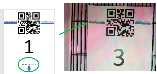
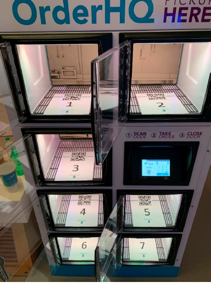
The cameras will read the QR codes and automatically assign a number to each camera. If the numbers are incorrectly assigned, users can set the Cam Value Override for each space using the up and down arrows under each image.
Verify that each camera has been assigned a space with the correct QR code and that there are no cameras left in the unassigned pool.

Note
The numbers should appear vertical (right side up). Numbers flipped 180 or 90 degrees off vertical indicate that cameras need to be rotated/adjusted until the correct image position is shown.
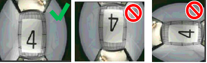
Select PASS to proceed. Select RETRY to restart the camera configuration process.
Verify that all doors are open and then click Complete. This will take the user to module and space configuration.
Module and Space configuration
The user will see a matrix of red squares indicating open doors. Close space 1 and click Verify Door.
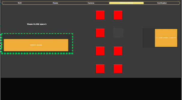
Repeat this until all doors are closed and the squares have changed to green indicating a closed door.
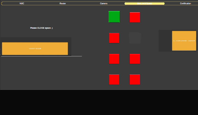
Click ALL DOORS VERIFIED - COMPLETE to finish module and space configuration.
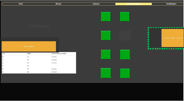
API Management
API Integrator and Central Routing
Send API Management Invitation
To start the process to send the invitation, the user who is going to send the invitation must log in with a master admin user.
After logging in, select the API Integrators option (If the option is not available, it may be because the user does not have the permissions or the Apex workspace is not selected).
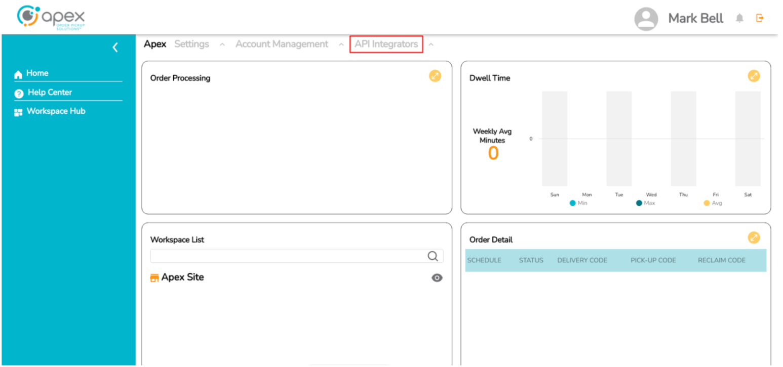
By clicking on the API Integrator option, the user will have the INVITE API INTEGRATOR button available to start the invitation process.

The first step for the invitation is to define the Corporate Name and the email of the user who will manage the API Integrator and click on the Invite button.
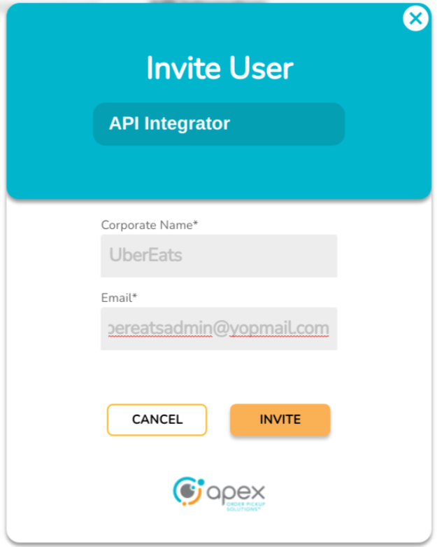
After clicking on the Invite button, a confirmation message is shown.
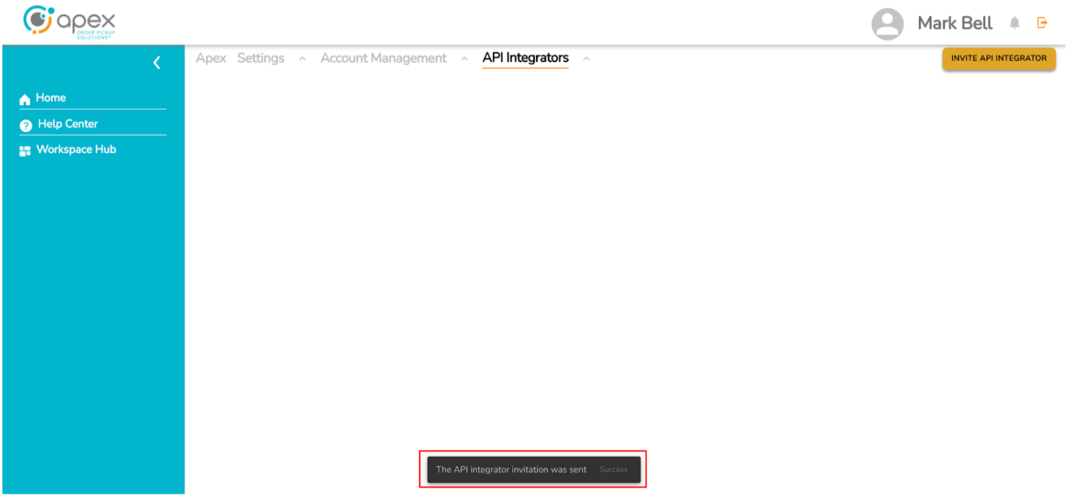
Use the Invitation Email and Login as API Integrator
The second part of the invitation is how to use the invitation email for the API Integrator. The new user must go to their inbox in their email and click the link to account update.
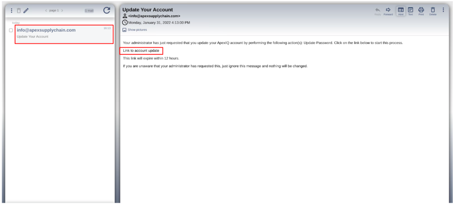
Next, the new user will start changing the password by clicking on the LET'S GO button.

The new user must set a password to log in to the Portal and click on the UPDATE button.

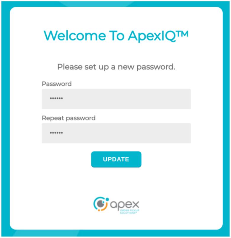
Finally the Portal shows a message to the user that the password was changed successfully and he must log in using his email and his new password.

Get Client ID and Client Secret
The third step in the invite is login with the new user to get the Keycloak information to make requests to the Apex systems. The new user must enter his username and his new password and click on the LOG IN button.

The new user will be redirected to the API Integrator dashboard which contains the Available Applications, Number of Hits and Documentation sections. To obtain the connection information, the user must click on the details icon, in the Details column of the Available Applications section.
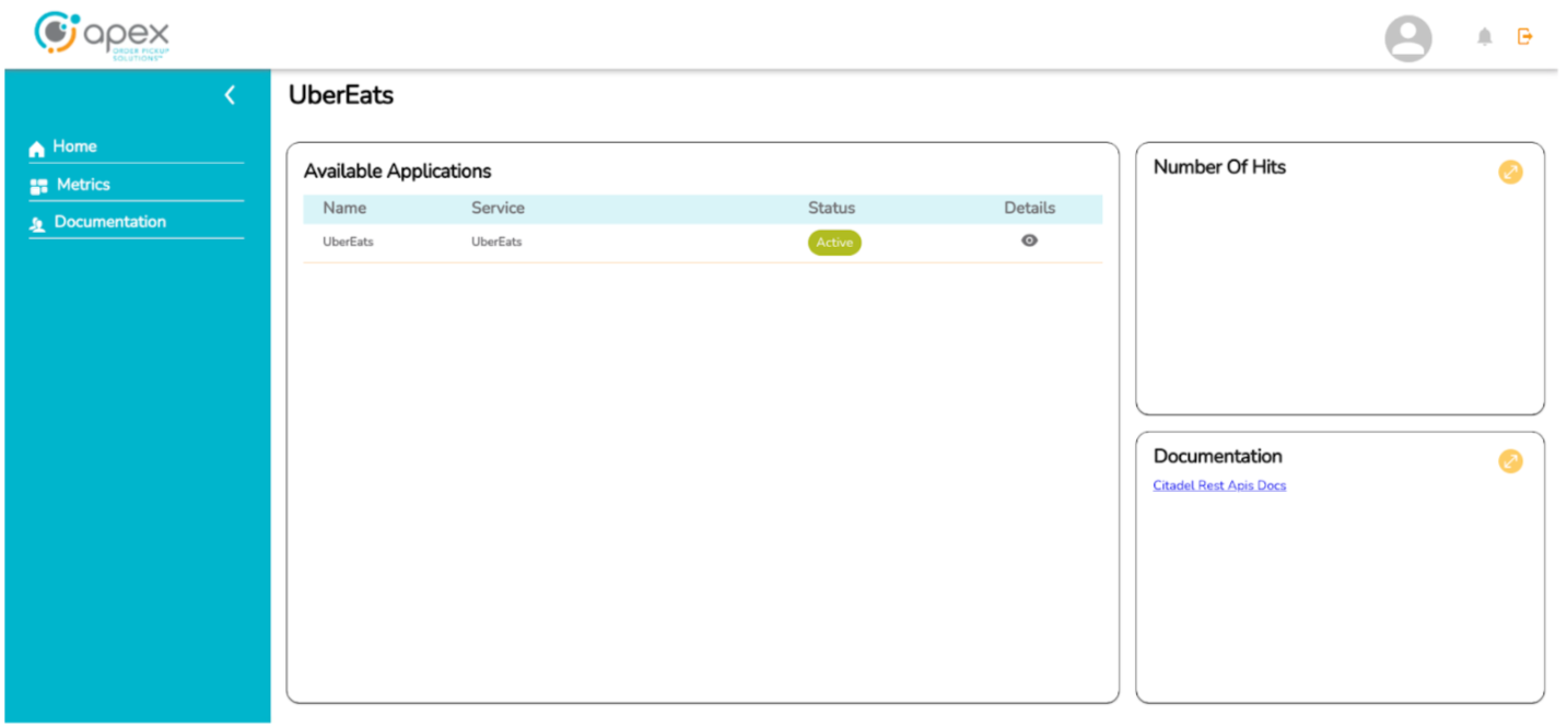
The Portal will open a popup with the application details. The connection data to be used will be the URL, the Client ID listed in the central table. To obtain the Client Secret the user must click on the CLIENT SECRET button (the client secret key is copied to the clipboard when the button is clicked).
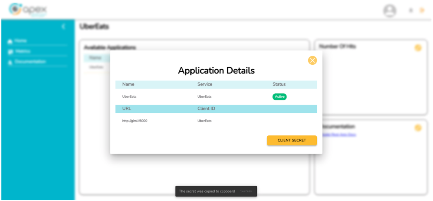
Assign the API Integration to a Site
To assign the API integrator to the site, the user must log in with a user account that has access to the Site Management section.
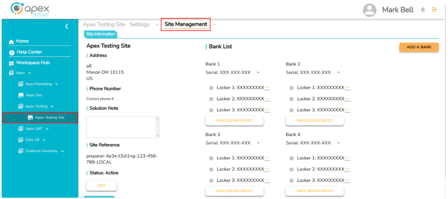
At the bottom the user is able to see the API Integrator section, in that section they will be able to assign the desired API Integrator to the site.
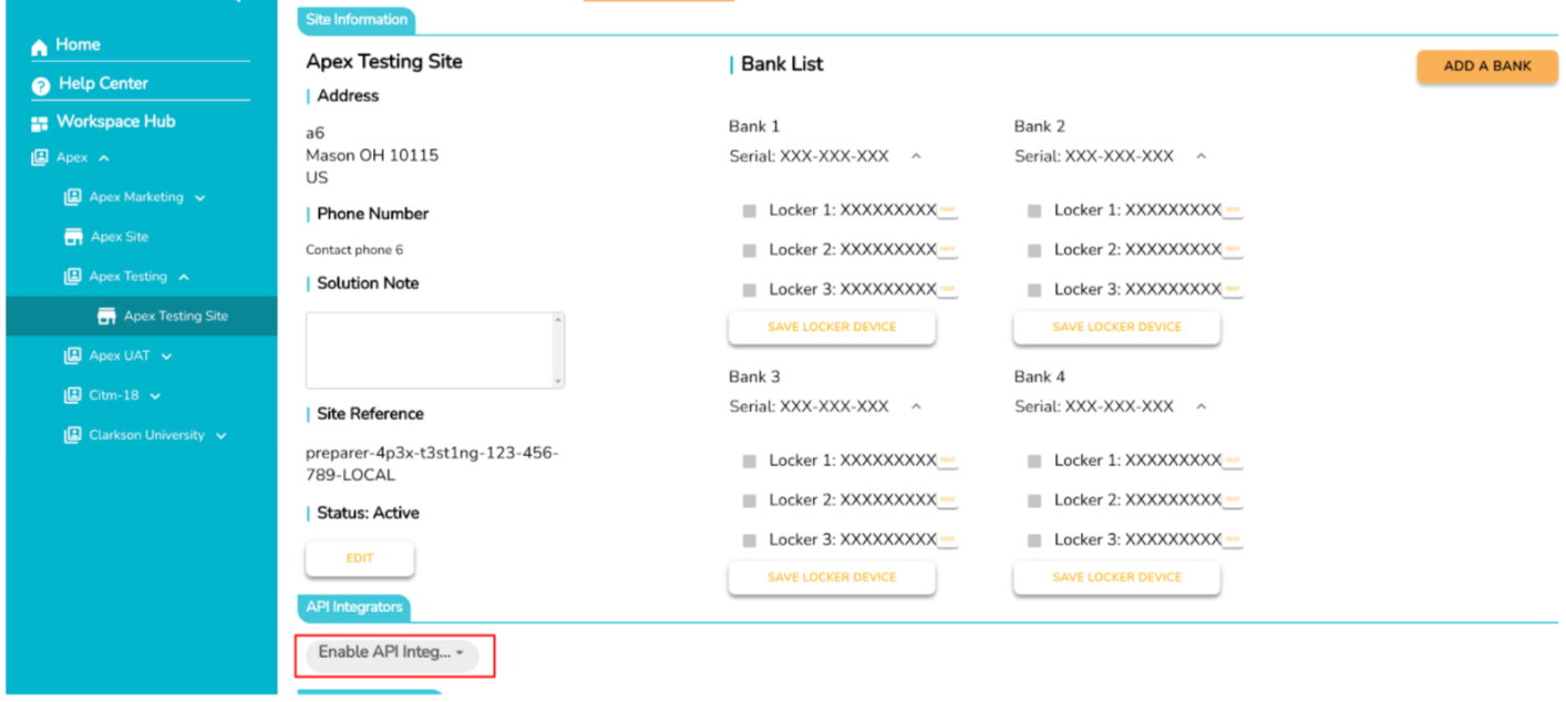
The user must pick the Integrator in the list and will receive a confirmation message (In this case UberEats was selected).
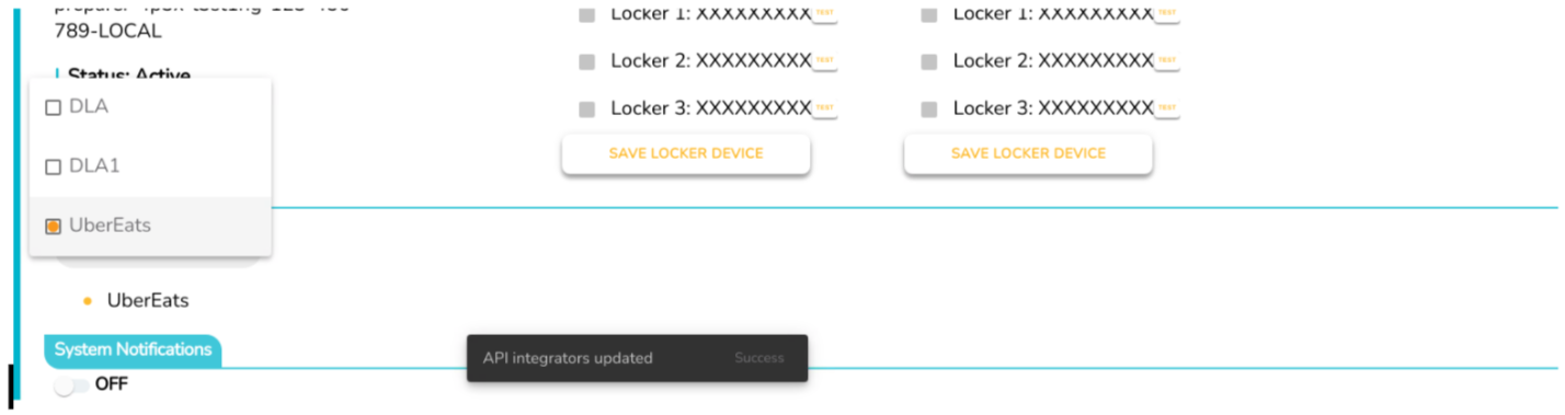
At the end, the Integrator will be in the list of added Integrators.
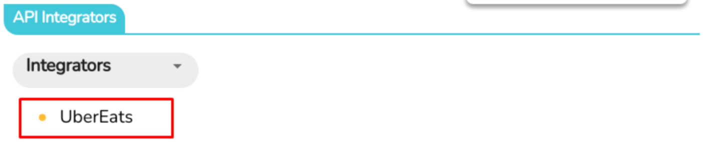
API Management
For a comprehensive overview of common scenarios and key components of API Management, please view the Rest APIs site.
Schedules
Token
Orders
Delivery Order
NUC BIOS Setup
In order to assure continuous uninterrupted operation of equipment, a quick BIOS change must be applied.
Press F2 during the boot up sequence to access the NUC BIOS settings.
Navigate to the Power tab.
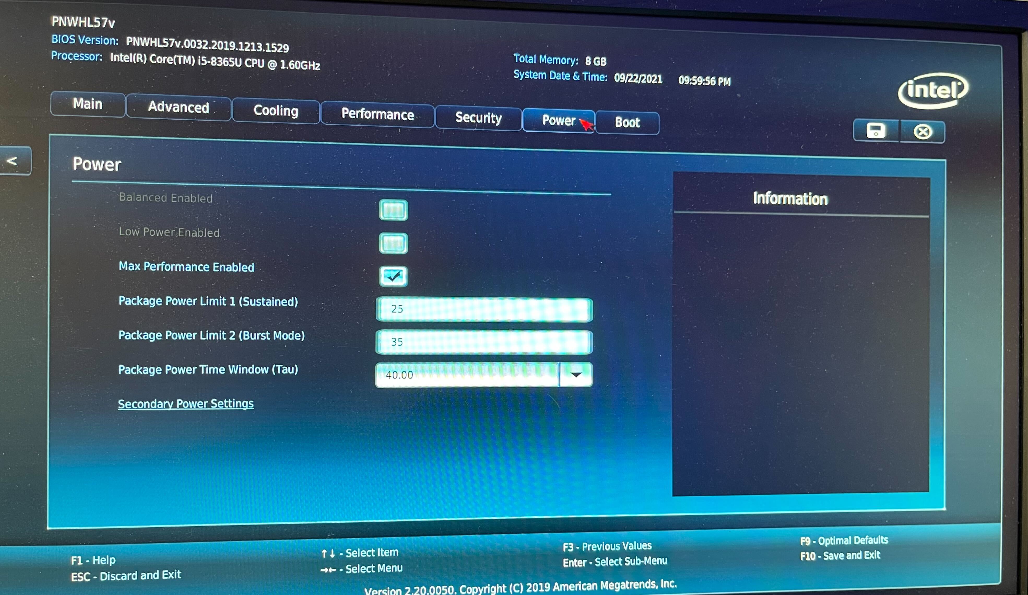
Navigate to Secondary Power Settings.
On the Secondary Power Settings menu, set the option for After Power Failure to Power On.
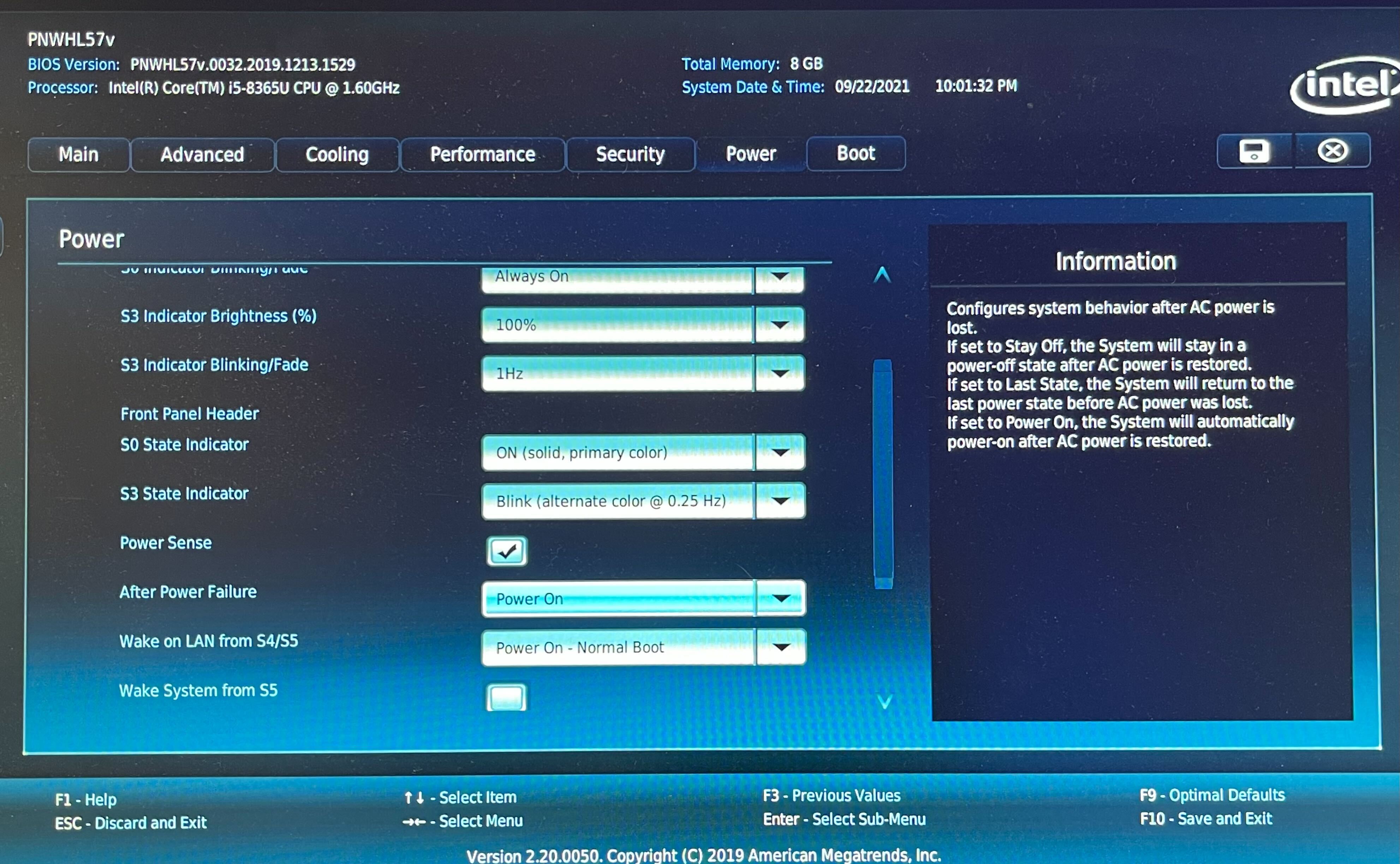
Press F10 to save changes and exit the BIOS.
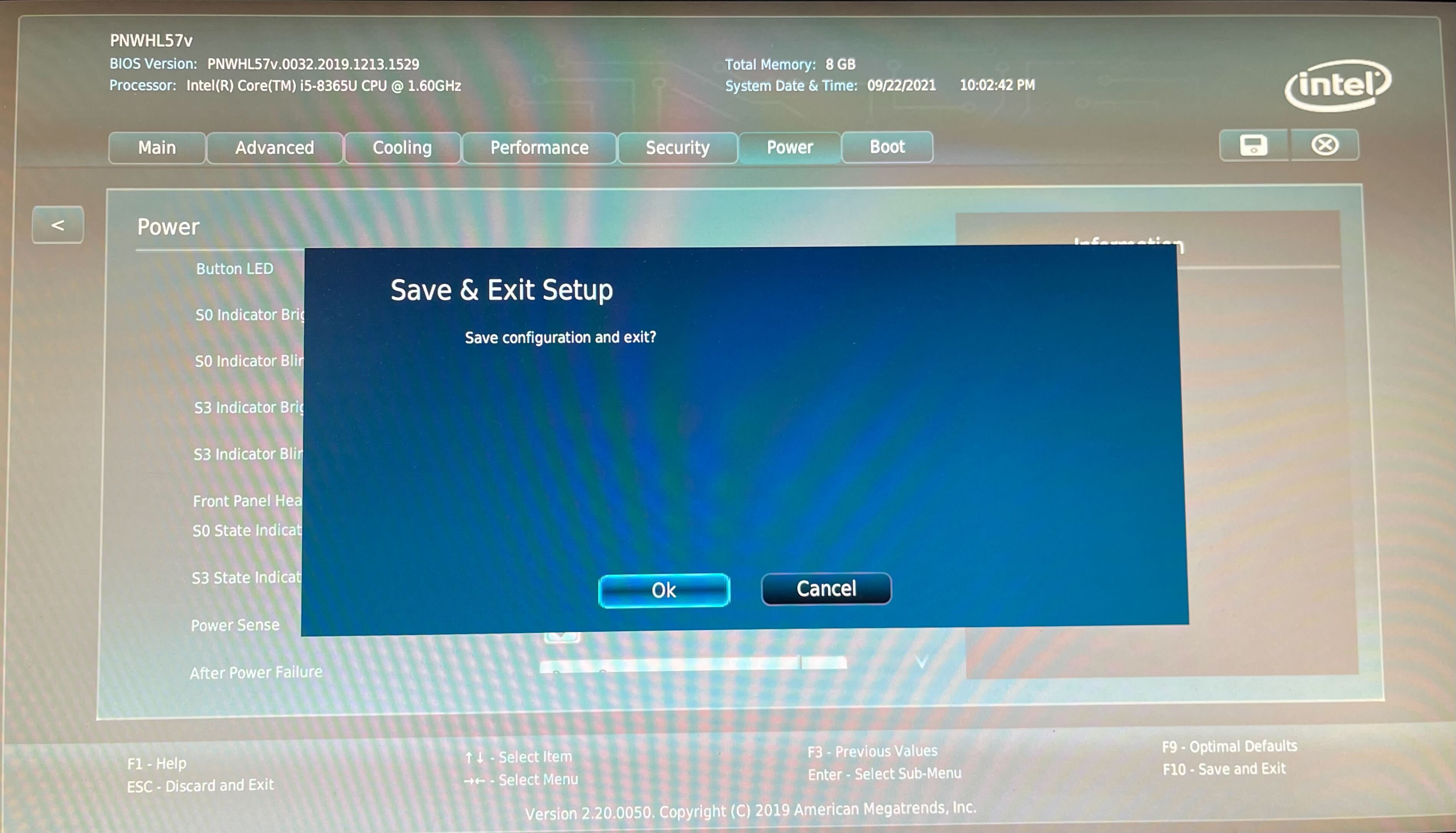
IEI BIOS Setup
In order to assure continuous uninterrupted operation of equipment, a quick BIOS change must be applied.
Press the Del key during the boot up sequence to access the IEI BIOS settings.
Navigate to the Boot tab.
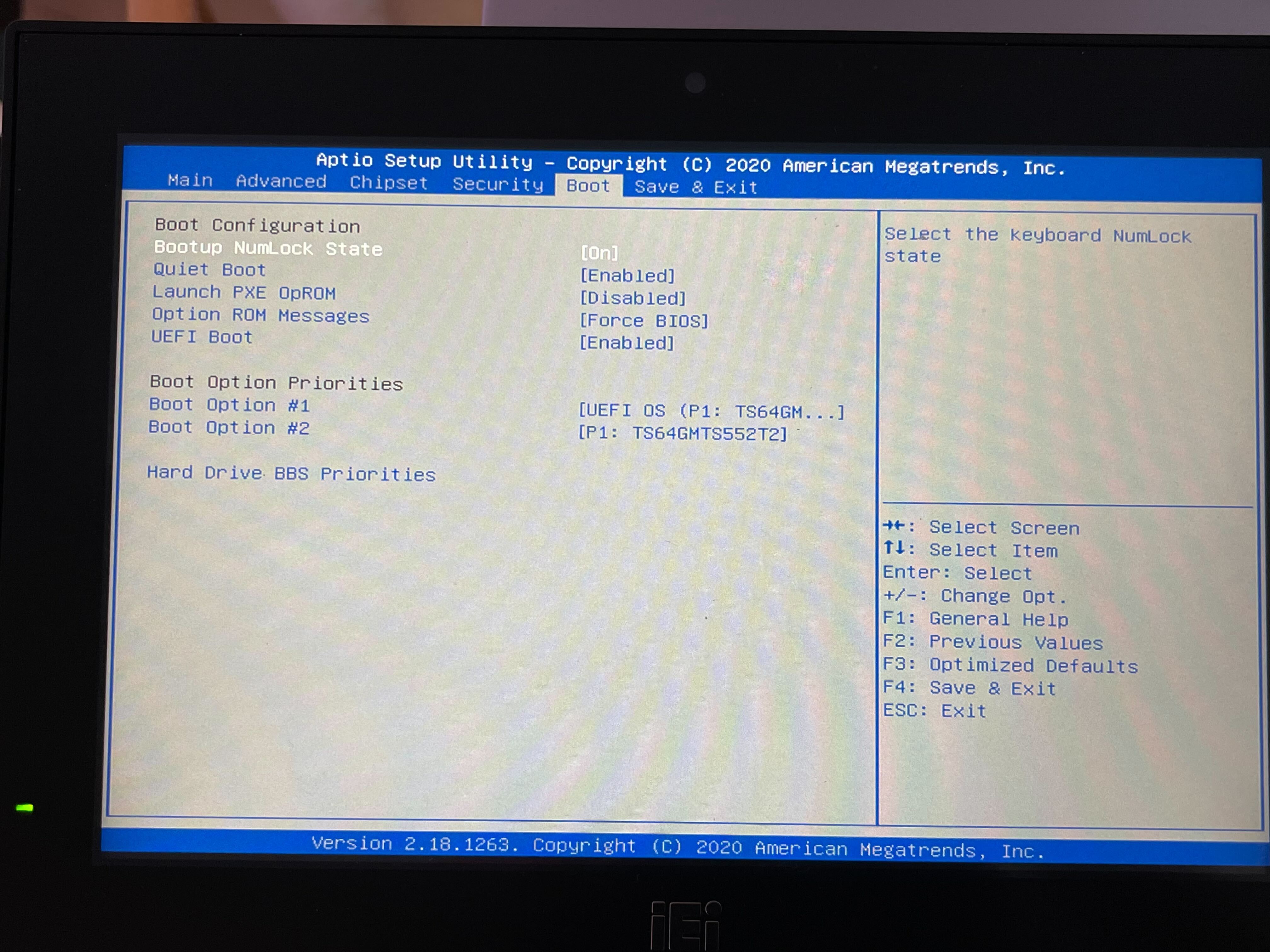
Set UEFI Boot to Enabled.
Press F4 to save changes and exit the BIOS.